EACA
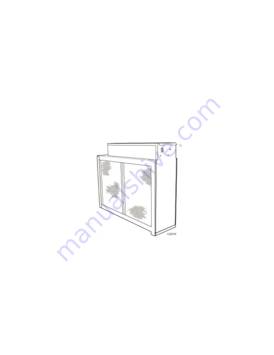
Electronic Air Cleaner
Sizes 0014, 0020, & 2020
Manual for:
Installation • Operation • Maintenance
CAUTION: Read installation instructions and rules carefully for safe operation.
Exercise the usual precautions when working with high voltage.
Form # EACA-1SI / II EACA-14-1 Date 07/02


