background image

32

• LOW suction pressure and frosting of the valve and/or

equalizer line may indicate a failed valve. However,

these symptoms may also indicate an undercharge of

refrigerant. Calculate the subcooling and superheat to

verify a failed valve or refrigerant charge issue. 

Repair

See Table 14 for suggestions of good practices regarding

regular repairs. See Table 15 for additional troubleshooting

information.

Moisture Check — 

To perform moisture check:

• Check that connectors are orientated “down” (or as rec-

ommended by equipment manufacturer).

• Arrange harnesses with “drip loop” under motor.

• Check if condensate drain is plugged.

• Check for low airflow (too much latent capacity).

• Check for undercharged condition.

• Check and plug leaks in return ducts, cabinet.

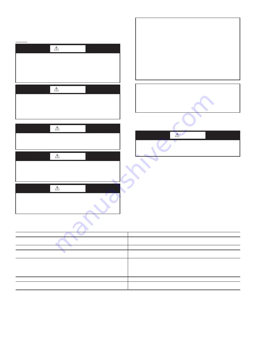
Table 14 — Good Practices

WARNING

Puron

®

 refrigerant (R-410A) operates at higher pressure

than R-22, which is found in other WSHPs. Tools such as

manifold gages must be rated to withstand the higher pres-

sures. Failure to use approved tools may result in a failure

of tools, which can lead to severe damage to the unit, injury

or death.

WARNING

Most TXVs are designed for a fixed superheat setting and

are therefore considered non-adjustable. Removal of the

bottom cap will not provide access for adjustment and can

lead to damage to the valve or equipment, unintended vent-

ing of refrigerant, personal injury, or possibly death.

CAUTION

Always recover the refrigerant from the system with suit-

able approved tools, recovery equipment, and practices

prior to attempting to remove or repair any TXV. 

CAUTION

Use caution when tightening the strap. The strap must be

tight enough to hold the bulb securely but caution must be

taken not to over-tighten the strap, which could dent, bend,

collapse or otherwise damage the bulb.

CAUTION

Puron

®

 refrigerant (R-410A) requires the use of synthetic

lubricant (POE oil). Do not use common tools on systems

that contain R-22 refrigerants or mineral oil. Contamina-

tion and failure of this equipment may result.

IMPORTANT: Due to the hygroscopic nature of the

POE oil in Puron refrigerant (R-410A) and other envi-

ronmentally sound refrigerants, any component replace-

ment must be conducted in a timely manner using

caution and proper service procedure for these types of

refrigerants. A complete installation instruction will be

included with each replacement TXV/filter drier assem-

bly. It is of critical importance these instructions are

carefully understood and followed. Failure to follow

these instructions can result in a system that is contami-

nated with moisture to the extent that several filter drier

replacements may be required to properly dry the

system.   

IMPORTANT: Repair of any sealed refrigerant system

requires training in the use of refrigeration tools and proce-

dures. Repair should only be attempted by a qualified ser-

vice technician. A universal refrigerant handling certificate

will be required. Local and/or state license or certificate

may also be required. 

CAUTION

Disconnect power from unit before removing or replacing

connectors, or servicing motor. Wait 5 minutes after dis-

connecting power before opening motor.

DO

DO NOT

Check motor, controls wiring, and connections thoroughly before replac-
ing motor.

Automatically assume the motor is bad.

Orient connectors down so water cannot get in. Install “drip loops.”

Locate connectors above 7 and 4 o’clock positions.

Use authorized motor and control model numbers for replacement.

Replace one motor or control model number with another (unless 
replacement is authorized).

Keep static pressure to a minimum by:

Using high efficiency, low-static filters.

Keeping filters clean.

Designing ductwork for minimum static and maximum comfort.

Improving ductwork when replacement is necessary.

Use high pressure drop filters.
Use restricted returns.

Size equipment wisely.

Oversize system then compensate with low airflow.

Check orientation before inserting motor connectors.

Plug in power connector backwards.
Force plugs.

Summary of Contents for Aquazone 50PTH024

Page 1: ... and servicing of air conditioning equipment can be hazardous due to system pressure and electrical components Only trained and qualified service personnel should install repair or service air conditioning equipment Untrained personnel can perform basic maintenance func tions such as cleaning coils and filters and replacing filters All other operations should be performed by trained service person...

Page 2: ... closet or mechanical room Space should be sufficient to allow return air to freely enter the space 9 Provide ready access to water valves and fittings and screwdriver access to unit side panels discharge collar and all electrical connections 10 Where access to side panels is limited pre removal of the control box side mounting screws may be necessary for future servicing STORAGE If the equipment ...

Page 3: ...se component failure due to added vibration UNIT 50PTH PTV 024 036 048 060 070 COMPRESSOR 1 each Scroll REFRIGERANT CHARGE VERTICAL oz 58 98 88 110 114 REFRIGERATION CHARGE HORIZONTAL ONLY oz 64 85 77 100 114 MAXIMUM WATER WORKING PRESSURE psig kPa 450 3 100 450 3 100 450 3 100 450 3 100 450 3 100 CONSTANT TORQUE FAN MOTOR BLOWER Fan Motor Type Speeds Constant Torque 5 speed Fan Motor Hp 0 33 0 75...

Page 4: ...4 Fig 1 50PTH024 070 Units Supply Air Configuration End Blow Dimensional Data ...

Page 5: ...5 Fig 2 50PTH024 070 Units Supply Air Configuration Straight Through Dimensional Data ...

Page 6: ...HAND RETURN J K L A A LEFT HAND RETURN F U T V W F U T W V ELECTRICAL KNOCKOUTS M N ELECTRICAL HEATER KNOCKOUT E G C D H B ELECTRIC HEATER IS OPTIONAL FEATURE CONDENSATE DRAIN CONNECTION 3 4 IN FPT NOTES 1 ALL DIMENSIONS ARE WITHIN 0 125 INCH 2 RETURN AND SUPPLY AIR DUCT FLANGES SHIPPED UNFOLDED 3 ALL DIMENSIONS ARE IN INCHES 4 SPECIFICATIONS SUBJECT TO CHANGE WITHOUT NOTICE ...

Page 7: ...uct connections on metal duct systems All metal ducting should be insulated with a minimum of 1 in duct insulation to avoid heat loss or gain and prevent condensate forming during the cooling operation Application of the unit to uninsulated ductwork is not recommended as the unit s performance will be adversely affected The factory provided air filter must be removed when using a filter back retur...

Page 8: ... a common loop maintained at 50 to 100 F The use of a closed circuit evaporative cooling tower with a secondary heat exchange be tween the tower and the water loop is recommended If an open type cooling tower is used continuously chemical treatment and filtering will be necessary In addition to complying with any applicable codes consid er the following for system piping Piping systems using water...

Page 9: ...ent to ppm IMPORTANT Failure to comply with the above required water quality and quantity limitations and the closed system application design requirements may cause damage to the tube in tube heat exchanger This damage is not the responsibility of the manufacturer CONDITION HX MATERIAL CLOSED RECIRCULATING OPEN LOOP AND RECIRCULATING WELL Scaling Potential Primary Measurement Above the given limi...

Page 10: ... obtained from alternate suppliers Supply and return hoses are fitted with swivel joint fittings at one end to prevent kink ing during installation Refer to Fig 7 for an illustration of a supply return hose kit Male adapters secure hose assemblies to the unit and risers In stall hose assemblies properly and check them regularly to avoid system failure and reduced service life Step 8 Wire Field Pow...

Page 11: ...60 197 253 1 11 7 58 3 2 8 17 4 25 2 8 17 4 25 8733801381 265 277 1 60 1 9 1 54 0 2 6 14 0 20 2 6 14 0 20 8733801385 208 230 3 60 197 253 1 6 5 55 4 2 8 10 9 15 2 8 10 9 15 8733801392 460 3 60 1 3 5 28 0 2 1 6 4 15 2 6 6 9 15 50PT036 8733902169 208 230 1 60 197 253 1 15 3 83 0 6 0 25 1 35 6 8 25 9 35 8733801382 265 277 1 60 1 13 0 72 0 4 9 21 2 30 5 5 21 8 35 8733801386 208 230 3 60 197 253 1 11 6...

Page 12: ...1 9 7 6 F1 F2 84 5 74 4 90 80 F3 F4 19 2 2 19 200 14 000 80 0 69 2 7 6 F1 F2 109 5 96 0 110 100 F3 F4 EH Electric Heat FLA Full Load Amps MCA Minimum Circuit Amps MOP Maximum Overcurrent Protection UNIT SIZE EH RATED kW STAGE HEATER WATTS HEATER AMPS MOTOR FLA A CIRCUIT MCA MOP 240 208 240 208 FUSES 240 208 240 208 024 4 8 1 4 800 3 600 20 0 17 3 2 8 28 5 25 1 30 30 036 4 8 1 4 800 3 600 20 0 17 3...

Page 13: ...EEZE SENSOR IS NOT INSTALLED A JUMPER SHALL BE INSTALLED BETWEEN THE FREEZE1 OR FREEZE2 SENSOR TERMINALS 7 ALARM OUTPUT DIP SWITCH MUST BE SET TO PULSE IF BLINKING T STAT SERVICE LIGHT IS DESIRED 8 DEFAULT SETTINGS FOR COMPLETE C BOARD FROM FACTORY SHOWN 9 ALARM OUTPUT IS NORMALLY OPEN NO DRY CONTACT IF 24 VAC IS NEEDED CONNECT R TO ALR COM TERMINAL 24 VAC WILL BE SENSED ON THE ALR OUT WHEN THE UN...

Page 14: ...EFAULT IF 15 F OPERATION IS REQUIRED JUMPER R30 MUST BE CUT IF FREEZE SENSOR IS NOT INSTALLED A JUMPER SHALL BE INSTALLED BETWEEN THE FREEZE1 OR FREEZE2 SENSOR TERMINALS 7 ALARM OUTPUT DIP SWITCH MUST BE SET TO PULSE IF BLINKING T STAT SERVICE LIGHT IS DESIRED 8 DEFAULT SETTINGS FOR COMPLETE C BOARD FROM FACTORY SHOWN 9 ALARM OUTPUT IS NORMALLY OPEN NO DRY CONTACT IF 24 VAC IS NEEDED CONNECT R TO ...

Page 15: ...N IS REQUIRED JUMPER R30 MUST BE CUT IF FREEZE SENSOR IS NOT INSTALLED A JUMPER SHALL BE INSTALLED BETWEEN THE FREEZE1 OR FREEZE2 SENSOR TERMINALS 8 ALARM OUTPUT DIP SWITCH MUST BE SET TO PULSE IF BLINKING T STAT SERVICE LIGHT IS DESIRED 9 DEFAULT SETTINGS FOR DELUXE D BOARD FROM FACTORY SHOWN 10 ALARM OUTPUT IS NORMALLY OPEN NO DRY CONTACT IF 24 VAC IS NEEDED CONNECT R TO ALR COM TERMINAL 24 VAC ...

Page 16: ... DEFAULT IF 15 F OPERATION IS REQUIRED JUMPER R30 MUST BE CUT IF FREEZE SENSOR IS NOT INSTALLED A JUMPER SHALL BE INSTALLED BETWEEN THE FREEZE1 OR FREEZE2 SENSOR TERMINALS 8 ALARM OUTPUT DIP SWITCH MUST BE SET TO PULSE IF BLINKING T STAT SERVICE LIGHT IS DESIRED 9 DEFAULT SETTINGS FOR DELUXE D BOARD FROM FACTORY SHOWN 10 ALARM OUTPUT IS NORMALLY OPEN NO DRY CONTACT IF 24 VAC IS NEEDED CONNECT R TO...

Page 17: ...IS NOT INSTALLED A JUMPER SHALL BE INSTALLED BETWEEN THE FREEZE1 OR FREEZE2 SENSOR TERMINALS 7 ALARM OUTPUT DIP SWITCH MUST BE SET TO PULSE IF BLINKING T STAT SERVICE LIGHT IS DESIRED 8 DEFAULT SETTINGS FOR COMPLETE C BOARD FROM FACTORY SHOWN 9 ALARM OUTPUT IS NORMALLY OPEN NO DRY CONTACT IF 24 VAC IS NEEDED CONNECT R TO ALR COM TERMINAL 24 VAC WILL BE SENSED ON THE ALR OUT WHEN THE UNIT IS IN ALA...

Page 18: ... BE INSTALLED BETWEEN THE FREEZE1 OR FREEZE2 SENSOR TERMINALS 7 ALARM OUTPUT DIP SWITCH MUST BE SET TO PULSE IF BLINKING T STAT SERVICE LIGHT IS DESIRED 8 DEFAULT SETTINGS FOR DELUXE D BOARD FROM FACTORY SHOWN 9 ALARM OUTPUT IS NORMALLY OPEN NO DRY CONTACT IF 24 VAC IS NEEDED CONNECT R TO ALR COM TERMINAL 24 VAC WILL BE SENSED ON THE ALR OUT WHEN THE UNIT IS IN ALARM CONDITION OUTPUT WILL BE PULSE...

Page 19: ...BETWEEN THE FREEZE1 OR FREEZE2 SENSOR TERMINALS 7 ALARM OUTPUT DIP SWITCH MUST BE SET TO PULSE IF BLINKING T STAT SERVICE LIGHT IS DESIRED 8 DEFAULT SETTINGS FOR COMPLETE C BOARD FROM FACTORY SHOWN 9 ALARM OUTPUT IS NORMALLY OPEN NO DRY CONTACT IF 24 VAC IS NEEDED CONNECT R TO ALR COM TERMINAL 24 VAC WILL BE SENSED ON THE ALR OUT WHEN THE UNIT IS IN ALARM CONDITION OUTPUT WILL BE PULSED IF PULSE I...

Page 20: ... BETWEEN THE FREEZE1 OR FREEZE2 SENSOR TERMINALS 8 ALARM OUTPUT DIP SWITCH MUST BE SET TO PULSE IF BLINKING T STAT SERVICE LIGHT IS DESIRED 9 DEFAULT SETTINGS FOR DELUXE D BOARD FROM FACTORY SHOWN 10 ALARM OUTPUT IS NORMALLY OPEN NO DRY CONTACT IF 24 VAC IS NEEDED CONNECT R TO ALR COM TERMINAL 24 VAC WILL BE SENSED ON THE ALR OUT WHEN THE UNIT IS IN ALARM CONDITION OUTPUT WILL BE PULSED IF PULSE I...

Page 21: ...e freeze protection sensor mounted close to condensing water coil monitors refrigerant temperature between condensing water coil and thermal expansion valve See Fig 19 If temperature drops below or remains at freeze limit trip for 30 seconds the controller will shut down the compressor and enter into a soft lock out condition The default freeze limit trip is 30 F how ever this can be changed to 15...

Page 22: ... 2 is dedicated to monitor the evapo rator coil it is recommended to leave the factory default setting on the board The Complete C controller will constantly moni tor the refrigerant temperature with the sensor mounted close to the condensing water coil between the thermal expansion valve and water coil If temperature drops below or remains at the freeze limit trip for 30 seconds the controller wi...

Page 23: ... 100 1 056 1 006 942 860 3 950 1 354 1 233 1 138 1 063 1 002 950 901 850 791 719 2 800 PL Fan Only 1 294 1 157 1 041 946 866 800 744 696 653 611 1 750 1 213 1 084 976 886 812 750 698 653 612 573 048 5 1800 FL 1 950 1 912 1 880 1 852 1 826 1 800 1 771 1 737 1 695 1 644 4 1600 1 774 1 738 1 703 1 669 1 635 1 600 1 562 1 521 1 475 1 423 3 1400 1 565 1 526 1 493 1 463 1 432 1 400 1 363 1 319 1 265 1 1...

Page 24: ...ernal Static Pressure in wg 0 10 0 20 0 30 0 40 0 50 0 60 0 70 0 80 0 90 1 00 024 PART LOAD High 725 A 725 725 725 725 725 725 725 725 Med 650 Normal A 650 650 650 650 650 650 650 650 Low 500 A 500 500 500 500 500 500 500 500 024 FULL LOAD High 950 A 950 950 950 950 950 950 950 950 Med 825 Normal A 825 825 825 825 825 825 825 825 Low 725 A 725 725 725 725 725 725 725 725 036 PART LOAD High 950 A 9...

Page 25: ...ompressor will start Unit Start Up Cooling Mode 1 Adjust the unit thermostat to the warmest position Slowly reduce the thermostat position until the compres sor activates 2 Check for cool air delivery at unit grille a few minutes after the unit has begun to operate 3 Verify that the compressor is on and that the water flow rate is correct by measuring pressure drop through the heat exchanger using...

Page 26: ...l is less than 1 to 2 in reverse the flow 8 Repeat this procedure until all air is purged 9 Restore power Antifreeze may be added before during or after the flush ing process However depending on when it is added in the process it can be wasted Refer to the Antifreeze section for more detail Loop static pressure will fluctuate with the seasons Pres sures will be higher in the winter months than du...

Page 27: ... test mode LOCKOUT WITH EMERGENCY HEAT While in Lock out mode if W becomes active then Emergency Heat mode will occur EMERGENCY HEAT In Emergency Heat mode terminal W is active while terminal Y is not Terminal G must be active in the 50PT units the fan will be run if W is energized EH1 is immediately turned on EH2 will turn on Units with Aquazone Deluxe D Control STANDBY FAN ONLY The compressor wi...

Page 28: ...ronment the equipment is used in In a single family home that is not under construction changing or clean ing the filter every 60 days may be sufficient In other applica tions such as motels where daily vacuuming produces a large amount of lint filter changes may be need to be as frequent as biweekly See Fig 1 3 for replacement filter sizes Note that horizontal units containing two filters are tap...

Page 29: ...2 FORCED CIRCULATION METHOD Fully open vent pipe when filling condenser The vent may be closed when condenser is full and pump is operating See Fig 23 Regulate flow to condenser with a supply line valve If pump is a nonoverloading type the valve may be fully closed while pump is running For average scale deposit allow solution to remain in con denser overnight For heavy scale deposit allow 24 hour...

Page 30: ...pressure exerted by the diaphragm will vary depending on the pressure inside of the sensing bulb As the temperature of and pressure within the bulb decreases the valve will modulate closed and restrict the refrigerant flow through the valve The result is less refrigerant in the evaporator and an increase in the superheat As the temperature at the bulb increases the dia phragm pressure will increas...

Page 31: ...bove FP2 faults in the cooling mode in combination with any of the symptoms listed above Some symptoms can mimic a failed TXV but may actually be caused be another problem Before conducting an analysis for a failed TXV the follow ing must be verified Confirm that there is proper water flow and water tem perature in the heating mode Confirm that there is proper airflow and temperature in the coolin...

Page 32: ...stems that contain R 22 refrigerants or mineral oil Contamina tion and failure of this equipment may result IMPORTANT Due to the hygroscopic nature of the POE oil in Puron refrigerant R 410A and other envi ronmentally sound refrigerants any component replace ment must be conducted in a timely manner using caution and proper service procedure for these types of refrigerants A complete installation ...

Page 33: ...cover refrigerant evacuate and recharge with fac tor recommended charge High pressure Check for defective or improperly calibrated high pressure switch Unit off on low pressure control Suction pressure too low In COOLING mode Lack of or inadequate airflow Entering air temperature is too cold Blower inoperative clogged filter or restrictions in ductwork In HEATING mode Lack of or inadequate water f...

Page 34: ...to discontinue or change at any time specifications or designs without notice and without incurring obligations Catalog No 04 53500104 01 Printed in U S A Form 50PT 5SI Pg 34 1218 6 14 Replaces NEW Carrier Corporation 2014 8733953040 ...

Page 35: ... FLUID AVAILABLE AT HEAT EXCHANGER Y N HAS PUMP BEEN TURNED ON AND ARE ISOLATION VALVES OPEN Y N HAS CONDENSATE CONNECTION BEEN MADE AND IS ATRAP INSTALLED Y N IS AN AIR FILTER INSTALLED Y N II START UP IS FAN OPERATING WHEN COMPRESSOR OPERATES Y N IF 3 PHASE SCROLL COMPRESSOR IS PRESENT VERIFY PROPER ROTATION PER INSTRUCTIONS Y N UNIT VOLTAGE COOLING OPERATION PHASE AB VOLTS PHASE BC VOLTS PHASE ...

Page 36: ...D FACTOR Btu hr SUPERHEAT SUCTION TEMPERATURE SUCTION SATURATION TEMPERATURE DEG F SUBCOOLING DISCHARGE SATURATION TEMPERATURE LIQUID LINE TEMPERATURE DEG F Use 500 for water 485 for antifreeze SUCTION COMPRESSOR DISCHARGE COAX EXPANSION VALVE F F AIR COIL F PSI FLUID OUT FLUID IN F PSI F LIQUID LINE PSI F SAT CONTACT CARRIER COMMERCIAL SERVICES OR PRODUCT MANAGEMENT FOR ACCEPTABLE PRESSURE DROP T...

Reviews: