14
Shutdown
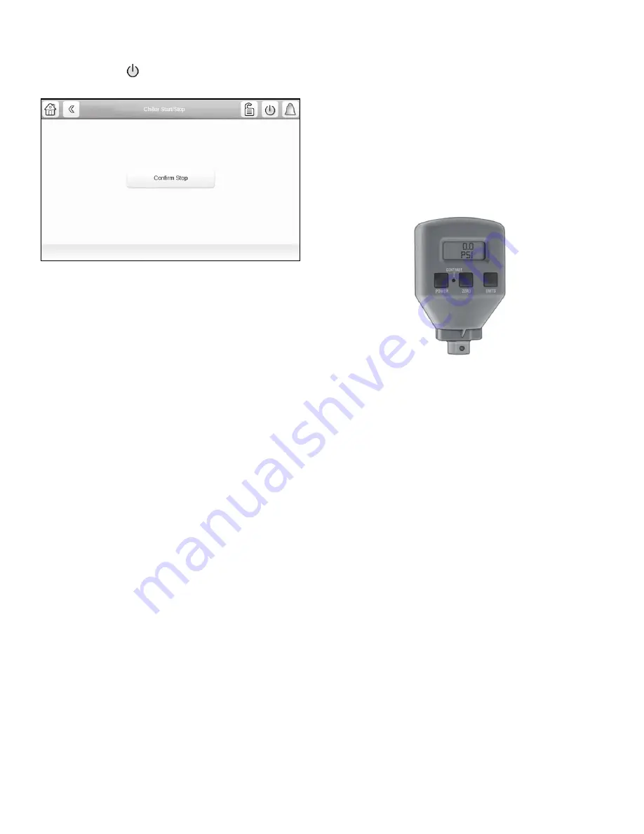
The unit can be stopped locally using the HMI by pressing the
green Start/Stop icon
. The Unit Start/Stop screen is displayed.
Press Confirm Stop (see Fig. 12).
Fig. 12 — Confirm Stop
Chiller shutdown begins if any of the following occurs:
• Local OFF button is pressed
• A recycle condition is present
• The time schedule has gone into unoccupied mode when in
Network or Local Schedule control mode
• The chiller protective limit has been reached and chiller is
in alarm
• The start/stop status (CHIL_S_S) is overridden to stop
from the network when in Network mode
If the chiller is normally shut down from running, soft stop shut-
down will be performed. The soft stop feature closes the guide
vanes of the compressor automatically if a non-alarm stop signal
occurs before the compressor motor is de-energized.
Any time the compressor is directed to stop (except in the cases of
a fault shutdown), the guide vanes are directed to close and VFD
is directed to minimum speed for variable speed compressor, and
the compressor shuts off when any of the following is true:
• PERCENT LOAD CURRENT (%) drops below the SOFT
STOP AMPS THRESHOLD
• ACTUAL GUIDE VANE OPENING drops below 4%
• 4 minutes have elapsed after initializing stop.
When any one of the above conditions is true, the shutdown se-
quence stops the compressor by deactivating the compressor start
relay. Then the guide vane shall be closed and stay at the fully
closed position, MBC will de-levitate the shaft once the shaft has
stopped rotating, and the chilled water/brine pump and condenser
water pump will be shut down.
BEFORE INITIAL START-UP
Job Data Required
• list of applicable design temperatures and pressures (product
data submittal) from the Equipment Sales Engineer who
sold the equipment
• chiller certified prints
• wiring diagrams
• diagrams and instructions for special controls or options
• 19MV Installation Instructions
Equipment Required
• mechanic’s tools (refrigeration)
• digital volt-ohmmeter (DVM)
• true RMS (root mean square) digital multimeter with clamp-
on current probe or true RMS digital clamp-on ammeter rated
for at least 575 vac and 1000 amps
• electronic refrigerant leak detector
• absolute pressure manometer or electronic micron gage
Fig. 13 — Digital Vacuum Gage
Remove Shipping Packaging
Remove any packaging material from the unit, VFD, and power
panels. Inspect the unit for damage that occurred during shipping
or installation. Document any damage that was identified.
Tighten All Gasketed Joints
Gaskets normally relax by the time the chiller arrives at the job-
site. Tighten all gasketed joints to ensure a leak-tight chiller (does
not apply to refrigerant joints covered by factory insulation).
Gasketed joints (excluding O-ring face seals*) may include joints
at some or all of the following:
• Waterbox covers
• Compressor first suction elbow flanges (at compressor and
at evaporator)
• BPHX discharge flange (option)
• Compressor discharge flange
• Isolation valve flanges (at condenser drain)
• ICP piping flanges
See Tables 3 and 4 for bolt torque requirements.
* O-ring face seals (ORFS) are factory torqued. See Table 5 for
(ORFS) torque requirements.
Summary of Contents for AquaEdge 19MV
Page 49: ...49 Fig 46 SIOB...
Page 50: ...50 Fig 47 IOB2...
Page 51: ...51 Fig 48 19MV Auxiliary Controls Wiring...


