background image

19

PRE-INSTALLATION

Unpack Unit — 

Remove the banding straps and lift the

cardboard lid. Remove the fascia, packed in bubble wrap, and
polystyrene packing pieces to expose the unit.

When removing the unit chassis from the box, the four cor-

ner brackets should be utilized for lifting. In order to protect the
fascia from dirt and damage, it should be returned to the box
until it is ready to be installed.

Blank Off Pieces — 

When branch ducting is to be used,

polystyrene pieces for blanking off fascia openings are includ-
ed with the fascia packing. Up to two opposing sides may be
blanked off. See Duct Collars in Installation section.

Positioning

The unit installation position should be selected with the fol-
lowing points in mind:

1. The appliance must be installed on a structure that is suit-

able to support the total weight of the appliance, piping,
and condensate.

2. Piping, electrical panel and condensate pump access pan-

el should be readily accessible for maintenance purposes.
A 2-ft clearance is recommended around the electrical
panel and condensate pump access panel.

3. The unit should not be positioned less than 5 ft from a

wall or similar obstruction, or in a position where the dis-
charge air could blow directly on to the thermostat. A 5 ft
clearance is required below the unit for service access.

4. The unit should not be positioned directly above any

obstructions.

5. The unit must be installed square and level.
6. The condensate drain should have sufficient downward

slope (1 inch in 100 in.) in any horizontal run between
unit and drain. Maximum condensate pump lift is
30 inches.

7. There should be sufficient room above the false ceiling

for installing the unit. Minimum distance as shown in
Fig. 18.

8. In case of high humidity, clogged or damaged condensate

piping, incorrect installation or faulty condensate pump,
water may drip from the unit. Do not install the appliance
where dripping water can cause damage.

Ceiling Opening Sizes — 

An opening in the false ceil-

ing will then have to be cut to the size shown in Table 2.

Table 2 — Ceiling Opening Dimensions

A cardboard template for ceiling cutout and rod positions is

included with the unit.

Positioning the Electro-Mechanical Thermo-
stat — 

In addition to positioning the unit correctly, it is very

important to locate the wall-mounted thermostat in the opti-
mum position to ensure good temperature control. Therefore,
the installation should be selected with the following points in
mind:

1. Position the thermostat approximately 48 in. above floor

level.

2. Do not position thermostat where it can be directly affect-

ed by the unit's discharge airstream.

3. Avoid external walls and drafts from windows and doors.
4. Avoid positioning near shelves and curtains as these re-

strict air movement.

5. Avoid heat sources e.g., direct sunlight, heaters, dimmer

switches and other electrical devices.

INSTALLATION

Hanger Bolts — 

The hanger bolts can now be installed at

the centers shown in Fig. 19. Use 

3

/

8

 in. all thread rod.

Check the strength of the unit mounting hanger bolts. Refer

to Table 1 for unit weights.

Installation Guide — 

An installation guide is included

in the Carrier Owner Information packet provided with the
unit. Prepare the installation guide by folding the flat metal
piece, by hand, along the perforations as shown in Fig. 20.
INSTALLATION GUIDE SETUP — The unit can now be
lifted onto the hanging rods and leveled at the correct distance
from the ceiling with the aid of the installation guide.

1. Hold the tab on the installation guide against the bottom

of the cassette case with the guide pointing away from the
cassette. See Fig. 21.

DANGER

Appliances must not be installed where they may be
exposed to potentially explosive or flammable atmosphere.

A

30 in.
MAX.

Fig. 18 — Minimum Distance to Ceiling

42WKN UNIT SIZE

DIMENSION A (in.)

08,12

12

3

/

4

18,20

11

1

/

2

33,36

13

1

/

2

a42-4049

42WKN UNIT SIZE

DIMENSIONS (in.)

08,12

23 in. x 23 in. 

18,20

34 in. x 34 in.

33,36

46 in. x 34 in.

IMPORTANT: Make sure the ceiling grid is supported sep-
arately from the appliance. The ceiling must not be sup-
ported by any part of the appliance, fascia or any associated
wiring or pipe work.

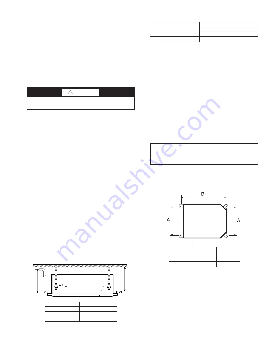
Fig. 19 — Hanger Bolt Mounting Dimensions

42WKN 

UNIT SIZE

DIMENSIONS (in.)

A

B

08,12

19

1

/

2

23

18,20

28

1

/

2

31

1

/

2

33,36

28

1

/

2

43

1

/

2

a42-4022

Summary of Contents for AIRSTREAM 42WKN

Page 1: ...TEMPERATURE CONTROL POWER FAILURE BATTERY BACKUP Alarms 34 ELECTRIC HEATER OVERHEAT PROTECTION HIGH CONDENSATE LEVEL ALARM NETWORK OPTION MICROPROCESSOR CONTROLLER 34 35 Master Slave Operation 34 Netw...

Page 2: ...data DANGER Appliances must not be installed where they may be exposed to potentially explosive or flammable atmosphere WARNING Improper installation adjustment alteration service or maintenance can...

Page 3: ...ube Quantity 1 1 1 1 1 1 Face Area sq ft 1 8 1 8 2 8 2 8 5 2 5 2 Nominal Airflow cfm High 350 350 630 700 970 1160 Medium 300 300 530 630 890 970 Low 260 260 500 530 785 890 Discharge 4 way 4 way 4 wa...

Page 4: ...1 8 3 3 4 2 1 16 2 5 8 A A VIEWA A 9 13 16 1 1 8 2 3 4 5 7 8 9 5 10 6 1 CWInlet 2 CWOutlet 3 HWCoil Inlet Optional 4 HWCoil Outlet Optional 5 Branch Duct Opening x3 6 Fresh Air Intake x2 7 Pump Inspe...

Page 5: ...13 16 8 11 16 1113 16 3 1 8 713 16 23 4 VIEWA A A A 2 5 1 4 10 5 6 7 8 9 3 5 3 8 1 CWCoil Inlet 2 CWCoil Outlet 3 HWCoil Inlet Optional 4 HWCoil Outlet Optional 5 Fresh Air Intake x3 6 Branch Duct Op...

Page 6: ...6 4 3 4 7 9 16 913 16 1 5 8 47 8 2 3 4 2 3 4 3 1 8 9 13 16 23 4 5 10 2 5 4 3 1 6 7 9 8 1 CWCoil Inlet 2 CWCoil Outlet 3 HWCoil Inlet Optional 4 HWCoil Outlet Optional 5 Fresh Air Intake x3 6 Branch Du...

Page 7: ...tments and settings being made from a hand held IR transmitter or optional pendant The controls include the following basic components PCB control board Infrared transmitter or optional pendant Infrar...

Page 8: ...Wiring Diagram Sizes 08 and 12 a42 4333 AL Alarm Relay AWG American Wire Gage BAT Battery CPM Condensate Pump CPU Central Processing Unit CW Chilled Water PCB Printed Circuit Board Factory Installed...

Page 9: ...Diagram Sizes 18 and 20 a42 4336 AL Alarm Relay AWG American Wire Gage BAT Battery CPM Condensate Pump CPU Central Processing Unit CW Chilled Water PCB Printed Circuit Board VM Vane Motor Factory Ins...

Page 10: ...Diagram Sizes 33 and 36 a42 4327 AL Alarm Relay AWG American Wire Gage BAT Battery CPM Condensate Pump CPU Central Processing Unit CW Chilled Water PCB Printed Circuit Board VM Vane Motor Factory Ins...

Page 11: ...agram Size 08 and 12 a42 4332 AL Alarm Relay AWG American Wire Gage BAT Battery CPM Condensate Pump CPU Central Processing Unit CW Chilled Water HTR Heat Relay HW Hot Water PCB Printed Circuit Board F...

Page 12: ...zes 18 and 20 AL Alarm Relay AWG American Wire Gage BAT Battery CPM Condensate Pump CPU Central Processing Unit CW Chilled Water HTR Heat Relay HW Hot Water PCB Printed Circuit Board VM Vane Motor Fac...

Page 13: ...izes 33 and 36 a42 4328 AL Alarm Relay AWG American Wire Gage BAT Battery CPM Condensate Pump CPU Central Processing Unit CW Chilled Water HTR Heat Relay HW Hot Water PCB Printed Circuit Board VM Vane...

Page 14: ...r Control Wiring Diagram Sizes 08 and 12 A42 4335 AL Alarm Relay AWG American Wire Gage BAT Battery CPM Condensate Pump CPU Central Processing Unit HW Hot Water PCB Printed Circuit Board VR Valve Rela...

Page 15: ...Control Wiring Diagram Sizes 18 and 20 A42 4339 AL Alarm Relay AWG American Wire Gage BAT Battery CPM Condensate Pump CPU Central Processing Unit PCB Printed Circuit Board VM Vane Motor VR Valve Rela...

Page 16: ...ol Wiring Diagram Sizes 33 and 36 A42 4329 AL Alarm Relay AWG American Wire Gage BAT Battery CPM Condensate Pump CPU Central Processing Unit HW Hot Water PCB Printed Circuit Board VM Vane Motor VR Val...

Page 17: ...ill operate the air vanes Med Large cassettes only OFF Pressing this button will switch the unit off TRANSMIT INDICATOR This symbol will flash when the system settings are transmitted MODE INDICATOR H...

Page 18: ...oor fan on cooling off and heating on Unit on timer operation off indoor fan on check main PCB battery Unit on timer operation on indoor fan on cooling and heating off Unit on timer operation on indoo...

Page 19: ...ble 2 Table 2 Ceiling Opening Dimensions A cardboard template for ceiling cutout and rod positions is included with the unit Positioning the Electro Mechanical Thermo stat In addition to positioning t...

Page 20: ...lation is pre cut to aid location and removal of the relevant section Rub hand across surface of insula tion to reveal exact location of knockout 3 Remove the metal knockout from the chassis 4 Attach...

Page 21: ...erminal strip 1 Push a small flat head screwdriver into the square hole on the terminal Press firmly until the screwdriver hits the back stop and opens the terminal See Fig 25 2 Remove approximately 3...

Page 22: ...Wire Gage CPM Condensate Pump CW Chilled Water Factory Installed Field Installed Terminal Block Component Terminal Connected Path 1 LEGEND NOTE Fan is wired to medium speed as a default To change the...

Page 23: ...age CPM Condensate Pump CW Chilled Water VM Vane Motor Factory Installed Field Installed Terminal Block Component Terminal Connected Path 1 LEGEND NOTE Fan is wired to medium speed as a default To cha...

Page 24: ...age CPM Condensate Pump CW Chilled Water VM Vane Motor Factory Installed Field Installed Terminal Block Component Terminal Connected Path 1 LEGEND NOTE Fan is wired to medium speed as a default To cha...

Page 25: ...AWG American Wire Gage CPM Condensate Pump VR Valve Relay Factory Installed Field Installed Terminal Block Component Terminal Connected Path 1 LEGEND NOTE Fan is wired to medium speed as a default To...

Page 26: ...rican Wire Gage CPM Condensate Pump VM Vane Motor VR Valve Relay Factory Installed Field Installed Terminal Block Component Terminal Connected Path 1 LEGEND NOTE Fan is wired to medium speed as a defa...

Page 27: ...rican Wire Gage CPM Condensate Pump VM Vane Motor VR Valve Relay Factory Installed Field Installed Terminal Block Component Terminal Connected Path 1 LEGEND NOTE Fan is wired to medium speed as a defa...

Page 28: ...ondensate Pump CW Chilled Water HTR Hot Water Relay HW Hot Water Factory Installed Field Installed Terminal Block Component Terminal Connected Path 1 LEGEND NOTE Fan is wired to medium speed as a defa...

Page 29: ...te Pump CW Chilled Water HTR Hot Water Relay HW Hot Water VM Vane Motor Factory Installed Field Installed Terminal Block Component Terminal Connected Path 1 LEGEND NOTE Fan is wired to medium speed as...

Page 30: ...te Pump CW Chilled Water HTR Hot Water Relay HW Hot Water VM Vane Motor Factory Installed Field Installed Terminal Block Component Terminal Connected Path 1 LEGEND NOTE Fan is wired to medium speed as...

Page 31: ...ither one of the 2 net work terminals marked The pendant connector and network terminal positions are illustrated in Fig 4 PRE START UP See the start up sheet example in Fig 37 A start up sheet is sup...

Page 32: ...r cooling 8 Where fitted check the operation of the hot water valve or the electrical heat elements by switching the system to the heating mode and forcing a call for heat 9 Allow chilled water to ent...

Page 33: ...o switch the unit on and transmit the new system settings Setting the Current Time 1 Press CLK TIMER button once CLOCK SET should begin flashing in the time display 2 Press either or button within the...

Page 34: ...es normal power outag es With no power the battery will last up to three months When the battery requires replacing the cool and heat status LEDs on the IR receiver will flash at 1 second intervals Al...

Page 35: ...ecommended Spares It is recommended that one complete set of air filters be kept on hand for use as needed DISASSEMBLY PROCEDURE Fan Removal 1 Unclip the grille catches and remove the grille s from th...

Page 36: ...a suitable container 4 Remove the self tapping screws securing the 2 insulated metal condensate tray support channels and pull the channels away from the condensate tray Pull the conden sate tray com...

Page 37: ...ities in every section of this trouble shooting guide first Replace the microprocessor only after all other avenues of investigation are exhausted Fans Will Not Run Loose wire Check all fan wire conne...

Page 38: ...to unit Faulty valve actuator Check actuator by manually opening and closing valve replace if faulty Faulty heater relay Check signals to relay and check action of relay contacts Replace relay or PCB...

Page 39: ...purchase order number Racine WI 53403 2552 1500 DeKoven Avenue n a n aA kW n a Electric Heat 500 CHARGE 1 QTY Maximum Discharge Temp 125 F Clearance to Combustibles 0 0 5 FIELD FACTORY CHARGE 0 LB TYP...

Page 40: ...ump Assembly Shown Inverted 9 Fan Motor Assembly 10 Coil Return Air Sensors Microprocessor Only 11 Grille 12 Label DESCRIPTION 13 Air Deflector Vanes 4 14 Filter 15 Fascia Assembly 16 Receiver Micropr...

Page 41: ...ondensate Tray Support 5 High Level Switch Shown Inverted 6 Condensate Pump Shown Inverted 7 Fan and Motor Assembly 8 Fan Inlet Ring 9 Grille 10 Infrared Receiver DESCRIPTION 11 Vane 12 Vane Motor Ass...

Page 42: ......

Page 43: ......

Page 44: ...ght to discontinue or change at any time specifications or designs without notice and without incurring obligations Catalog No 04 53420008 01 Printed in U S A Form 42WKN 7SI Pg 44 4 13 Replaces 42WKN...

Reviews: