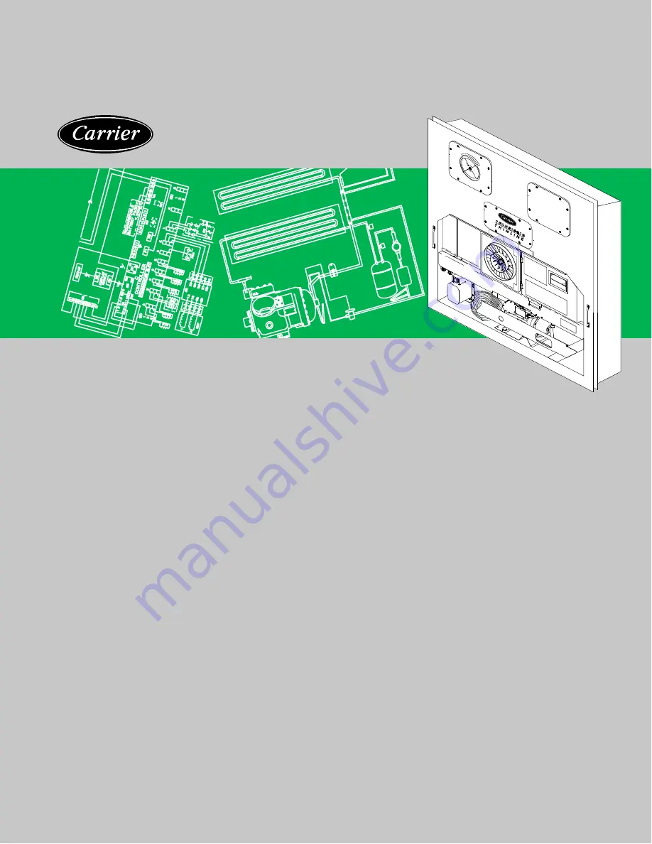
T--317 Rev A
OPERATION AND SERVICE
for
69NT40--541--200 TO 299
Container Refrigeration Units
Container Refrigeration
r
Page 1: ...T 317 Rev A OPERATION AND SERVICE for 69NT40 541 200 TO 299 Container Refrigeration Units Container Refrigeration r ...
Page 2: ...OPERATION AND SERVICE MANUAL CONTAINER REFRIGERATION UNIT Models 69NT40 541 200 to 299 ...
Page 3: ...trical safety devices e g bridging an overload or using any sort of jumper wires Problems with the system should be diagnosed and any necessary repairs performed by qualified service personnel When performing any arc welding on the unit or container disconnect all wire harness connectors from the modules in both control boxes Do not remove wire harness from the modules unless you are grounded to t...
Page 4: ...re turning power OFF and disconnecting power plug WARNING Oakite No 32 is an acid Be sure that the acid is slowly added to the water DO NOT PUT WATER INTO THE ACID this will cause spattering and excessive heat WARNING Wear rubber gloves and wash the solution from the skin immediately if accidental con tact occurs Do not allow the solution to splash onto concrete WARNING Always turn OFF the unit ci...
Page 5: ...FROST mode as long as the emergency defrost switch is in the DEFROST position To prevent cargo damage the operator must monitor con tainer temperature and manually cycle op eration as required to maintain temperature within required limits CAUTION To prevent trapping liquid refrigerant in the manifold gauge set be sure set is brought to suction pressure before disconnecting CAUTION Removing the co...
Page 6: ...ler programming port CAUTION Do not allow moisture to enter wire splice area as this may affect the sensor resis tance CAUTION Do not allow the recorder stylus to snap back down The stylus arm base is spring loaded and damage may occur to the chart or the stylus force may be altered CAUTION The inside mechanism of the recorder particularly the inside of the element housing should never be oiled ho...
Page 7: ... Pressure Readout 1 1 1 3 6 USDA 1 1 1 3 7 Interrogator 1 1 1 3 8 Remote Monitoring 1 1 1 3 9 Communications 1 1 1 3 10 Compressor 1 1 1 3 11 Condenser Coil 1 2 1 3 12 Autotransformer 1 2 1 3 13 Temperature Recorder 1 2 1 3 14 Gutters 1 2 1 3 15 Handles 1 2 1 3 16 Thermometer Port 1 2 1 3 17 Water Cooling 1 2 1 3 18 Back Panels 1 2 1 3 19 460 Volt Cable 1 2 1 3 20 230 Volt Cable 1 2 1 3 21 Cable R...
Page 8: ...y Pad 3 2 3 1 2 Display Module 3 2 3 1 3 Controller 3 3 3 2 CONTROLLER SOFTWARE 3 3 3 2 1 Configuration Software Configuration Variables 3 3 3 2 2 Operational Software Function Codes 3 3 3 3 MODES OF OPERATION 3 4 3 3 1 Temperature Control Perishable Mode 3 4 3 3 2 Evaporator Fan Operation 3 4 3 3 3 Defrost Interval 3 4 3 3 4 Failure Action 3 4 3 3 5 Generator Protection 3 4 3 3 6 Condenser Pressu...
Page 9: ...sh Air Makeup Vent 4 2 4 3 2 Lower Fresh Air Makeup Vent 4 2 4 3 3 Fresh Air Position Sensor 4 2 4 4 CONNECT WATER COOLED CONDENSER 4 2 4 4 1 Water Cooled Condenser with Water Pressure Switch 4 2 4 4 2 Water Cooled Condenser with Condenser Fan Switch 4 3 4 5 CONNECT REMOTE MONITORING RECEPTACLE 4 3 4 6 STARTING AND STOPPING INSTRUCTIONS 4 3 4 6 1 Starting the Unit 4 3 4 6 2 Stopping the Unit 4 3 4...
Page 10: ...ALVES 6 1 6 3 MANIFOLD GAUGE SET 6 1 6 4 REFRIGERANT RECOVERY 6 2 6 5 REFRIGERANT LEAK CHECKING 6 3 6 6 EVACUATION AND DEHYDRATION 6 3 6 6 1 General 6 3 6 6 2 Preparation 6 3 6 6 3 Procedure Complete system 6 3 6 7 REFRIGERANT CHARGE 6 4 6 7 1 Checking the Refrigerant Charge 6 4 6 7 2 Adding Refrigerant to System Full Charge 6 4 6 7 3 Adding Refrigerant to System Partial Charge 6 4 6 7 4 Emergency...
Page 11: ... Procedure 6 17 6 18 2 Checking The Stepper valve 6 18 6 18 3 Checking The Controller 6 18 6 19 AUTOTRANSFORMER 6 18 6 20 POWER FACTOR CORRECTOR CAPACITORS PFC 6 19 6 21 CONTROLLER 6 19 6 21 1 Handling Controller 6 19 6 21 2 Controller Trouble Shooting 6 20 6 21 3 Controller Programming Procedure 6 20 6 21 4 Removing and Installing the Controller 6 21 6 21 5 Battery Replacement 6 21 6 22 VENT POSI...
Page 12: ... 7 Figure 4 8 Defrost 4 8 Figure 6 1 Piercing Valve 6 1 Figure 6 2 Manifold Gauge Set 6 2 Figure 6 3 Manifold Gauge Set Connection 6 2 Figure 6 4 Vacuum Pump Connections 6 5 Figure 6 5 Compressor 6 6 Figure 6 6 Exploded View of Valve Plate 6 7 Figure 6 7 Bottom Plate Removed 6 7 Figure 6 8 Oil Pump and Bearing Head 6 8 Figure 6 9 Low Profile Oil Pump 6 8 Figure 6 10 Motor End Cover 6 8 Figure 6 11...
Page 13: ...7 5 UNIT WIRING DIAGRAM 7 6 LIST OF TABLES TABLE NUMBER Page Table 2 1 Safety and Protective Devices 2 9 Table 3 1 Key Pad Function 3 2 Table 3 2 DataCORDER Configuration Variables 3 8 Table 3 3 DataCORDER Standard Configurations 3 8 Table 3 4 Controller Configuration Variables 3 13 Table 3 5 Controller Function Codes 3 14 Table 3 6 Controller Alarm Indications 3 18 Table 3 7 Controller Pre Trip T...
Page 14: ...1 3 OPTION DESCRIPTION Various options may be factory or field equipped to the base unit These options are listed in the tables and described in the following subparagraphs 1 3 1 Battery The refrigeration controller may be fitted with standard replaceable batteries or a rechargeable battery pack 1 3 2 Dehumidification The unit may be fitted with a humidity sensor This sensor allows setting of a hu...
Page 15: ...he plug options tailor the cables to each customers requirements 1 3 21 Cable Restraint Various designs are available for storage of the power cables These options are variations of the compressor section front cover 1 3 22 Upper Air Fresh Air Make Up The unit may be fitted with an upper fresh air makeup assembly The fresh air makeup assembly is available with a Vent Positioning Sensor VPS and may...
Page 16: ...up Vent The function of the upper or lower makeup air vent is to provide ventilation for commodities that require fresh air circulation 1 2 3 6 4 9 5 10 13 7 14 12 8 11 1 Access Panel Evap Fan 1 2 Access Panel Heater Thermostatic Expansion Valve 3 Fork Lift Pockets 4 Control Box 5 Compressor 6 Unit Serial Number Model Number and Parts Identification Number PID Plate 7 Condenser Fan 8 TransFRESH Co...
Page 17: ...mponents are accessible by removing the upper rear panel as shown in the illustration or by removing the front access panels 17 16 14 15 1 2 3 4 6 7 9 10 13 18 19 11 8 12 5 ALTERNATE USDA LOCATION HTT Alternate Location 1 Evaporator Fan Motor 1 2 Return Recorder Sensor 3 Return Temperature Sensor 4 Humidity Sensor 5 Mechanical Recorder Bulb 6 Evaporator Fan Motor 2 7 Defrost Temperature Sensor 8 H...
Page 18: ...r and ambient sensor are located at the right side of the compressor 1 2 3 4 5 6 7 10 13 9 12 14 11 15 8 1 Power Autotransformer TRANS 2 Power Cables and Plug 3 Compressor Sight Glass View Port 4 Compressor Guard 5 Supply Temperature Sensor STS 6 Ambient Sensor AMBS 7 Discharge Pressure Regulator Valve 8 Suction Line Process Tube 9 Quench Expansion Valve 10 Stepper Motor Suction Modulation Valve S...
Page 19: ... and filter drier The condenser fan pulls air in the bottom of thecoil andit is discharged horizontally out through the condenserfan grille 5 6 7 11 1 2 4 3 8 10 9 1 Grille and Venturi Assembly 2 Condenser Fan 3 Key 4 Condenser Fan Motor 5 Condenser Coil Cover 6 Condenser Coil 7 Condenser Motor Mounting Bracket 8 Receiver 9 Sight Glass Moisture Indicator 10 Filter Drier 11 Quench Valve Figure 2 4 ...
Page 20: ...er drier water couplings and water pressure switch The water cooled condenser replaces the standard unit receiver 7 8 1 2 3 4 6 9 5 1 Water Cooled Condenser 2 Rupture Disc 3 Condenser Pressure Transducer CPT 4 Filter Drier 5 Moisture Liquid Indicator Sight Glass 6 Coupling Water In 7 Self Draining Coupling Water Out 8 Liquid Line Process Tube 9 Water Pressure Switch WP Figure 2 5 Water Cooled Cond...
Page 21: ...ication and return information over the main power line Refer to the master system technicalmanual for further information 17 18 13 15 16 1 2 3 4 5 6 8 10 7 9 14 11 12 1 Compressor Phase A Contactor 2 Compressor Phase B Contactor 3 Heater Contactor 4 Display Module 5 Communications Interface Module 6 Controller DataCORDER Module Controller 7 Key Pad 8 Remote Monitoring Receptacle 9 Controller Batt...
Page 22: ...e installation instructions included with the replacement part for additional information f Fusible Plug Melting point 99 _C 210 _F Torque 6 2 to 6 9 mkg 45 to 50 ft lbs g Sight Glass Moisture Indicator Torque 8 9 to 9 7 mkg 65 to 70 ft lbs h Rupture Disc Bursts at 35 5 kg cm 500 5 psig Torque P N 14 00215 03 1 4 to 2 mkg 10 to 15 ft lbs i Condenser Pressure Transducer Condenser Fan Starts The con...
Page 23: ...h e Evaporator Coil Heaters Number of Heaters 6 Rating 750 watts 5 10 each 230 vac Resistance cold 66 8 to 77 2 ohms 20 _C 68 _F Type Sheath f Evaporator Fan Motor s 380 vac 50 hz 460 vac 60 hz Full Load Amps High Speed 1 6 2 0 Full Load Amps Low Speed 0 8 1 0 Nominal Horsepower High Speed 0 70 0 84 Nominal Horsepower Low Speed 0 09 0 11 Rotations Per Minute High Speed 2850 rpm 3450 rpm Rotations ...
Page 24: ... Protector s IP EM Table 2 1 Safety and Protective Devices UNSAFE CONDITION SAFETY DEVICE DEVICE SETTING Circuit Breaker CB 1 Manual Reset Trips at 29 amps 460 vac Excessive current draw Circuit Breaker CB 2 50 amp Manual Reset Trips at 62 5 amps 230 vac Circuit Breaker CB 2 70 amp Manual Reset Trips at 87 5 amps 230 vac Excessive current draw in the control circuit Fuse F3A F3B 7 5 amp rating Exc...
Page 25: ...e to thecompressor The thermostatic expansion valve is activated by the bulb strapped to the suction line near the evaporator outlet The valve maintains a constant superheat at the coil outlet regardless of load conditions During periods of low load the suction modulating valve decreases flow of refrigerant to the compressor This action balances the compressor capacity with the load and prevents o...
Page 26: ...b 8 Heat Exchanger 9 Rupture Disc 10 Moisture Liquid Indicator 11 Condenser Pressure Transducer CPT 12 Filter Drier 13 Water Cooled Condenser 14 Receiver 15 Suction Modulation Valve SMV 16 Quench Expansion Valve 17 Process Tube 1 2 3 4 5 6 7 8 9 10 11 12 13 15 16 17 17 1 2 3 4 5 6 7 8 9 10 12 15 16 17 17 14 Circuit with Water Cooled Condenser Circuit with Receiver Figure 2 7 Refrigeration Circuit ...
Page 27: ...graph 3 2 Coverage of the DataCORDER software is provided in paragraph 3 6 The key pad and display module serve to provide user access and readouts for both of the controller functions temperature control and DataCORDER The functions are accessed by key pad selections and viewed on the display module The components are designed to permit ease of installation and removal TO DISPLAY CONTROL MODULE D...
Page 28: ...ller Arrow Up Change or scroll a selection upward Pre trip advance or test interruption Arrow Down Change or scroll a selection down ward Pre trip repeat backward Return Supply Displays non controlling probe tem perature momentary display _C _F Displays alternate English Metric scale momentary display When set to _F pressure is displayed in psig and vacuum in hg P appears after the value to indica...
Page 29: ... modify the Configuration Software Variables Operating Soft ware Function Codes and Alarm Code Indications d Provide a Pre Trip step by step checkout of refrigera tion unit performance including proper component operation electronic and refrigeration control opera tion heater operation probe calibration pressure limiting and current limiting settings e Provide battery powered ability to access or ...
Page 30: ...al to 12 hours for the first two defrosts once the return probe is reading below the frozen setpoint and then adjust to 24 hours thereafter All defrost interval times reflect the number of compressor runtime hours since the last defrost de ice cycle The minimum defrost interval under the automatic setting is 3 hours while the maximum is 24 In frozen mode the amount of wall clock time necessaryto a...
Page 31: ...ns are satisfied the controller will activate the heat relay to begin dehumidification 1 The humidity sensor reading is above the set point 2 The Supply air temperature is less than 0 25_C above set point 3 The heater debounce timer three minutes has timed out 4 Heater termination thermostat HTT is closed If the above conditions remain true for at least one hour the evaporator fans will switch fro...
Page 32: ...revent rapid cycling of the compressor a three minute compressor off time must be satisfied before the compressor will restart Under a condition of rapidly changing return air temperature the time delay may allow the return air temperature to rise slightly above set point temperature before the compressor can restart 3 3 14 Frozen Mode Economy In order to activate economy frozen mode operation a f...
Page 33: ... pad selections and viewed on the display module The unit is also fitted with interrogation connections see Figure 3 1 which may be used with the Carrier Transicold Data Reader to down load data A personal computer with Carrier Transicold Data View software may also be used to download data and configure settings The DataCORDER consists of Configuration Software Operational Software Data Storage M...
Page 34: ...E The DataCORDER software uses the supply and return recorder sensors The temperature control software uses the supply and return temperature sensors b Generic Mode The generic recording mode allows user selection of the network data points to be recorded The user may select up to a total of eight data points for recording A list of the data points available for recording follows Changing the conf...
Page 35: ...52 Bill of Lading 1 Origin Origin Date Destination Discharge Date Comment DataLine Tool Probe Calibration Readings USDA1 0 0 USDA2 0 0 USDA3 0 0 Cargo 0 0 Temperature Units Centigrade ________________________________________________________________________________________ May 31 2001 Setpoint 1 66 Container Serial 04189552 9 Sensors Logged at 15 Minute Interval Sensor Format Resolution Figure 3 5 ...
Page 36: ... 1 Normal AC power The DataCORDER is powered up when the unit is turned on via the stop start switch 2 Controller DC battery pack power If a battery pack is installed the DataCORDER will power up for communication when an interrogation cable is plugged into an interrogation receptacle 3 External DC battery pack power A 12 volt battery pack may also be plugged into the back of the interrogation cab...
Page 37: ..._YYMMDDHHMM dcx where XXXXNNNNNNNN is the container number and YYMMDDHHMM is the year month day hour and minute of the last event record or sensor data record contained in the transfer Note If the unit does not have a valid container num ber DataBank will subsitute the container num ber with CTDExxxxxxx where the last seven digits will correspond to the last seven digits in the controller part num...
Page 38: ...containers This probe should be placed in a center carton at one half the height of the load Sensor 3 Place in pulp of product five feet from the end of the load for 40 foot containers or three feet from the end of the load for 20 foot containers This probe should be placed in a carton at a side wall at one half the height of the load e To initiate USDA Recording connect the personal computer and ...
Page 39: ...ransformer Out In CnF22 Economy Mode Option OFF Std Full CnF23 Defrost Interval Timer Save Option noSAv SAv CnF24 Advanced Pre Trip Enhanced Test Series Option Auto Auto2 Auto 3 CnF25 Pre Trip Test Points Results Recording Option rSLtS dAtA CnF26 Heat Lockout Change Option Set to 10_C Set to 5_C CnF27 Suction Temperature Display Option Out In CnF28 Bulb Mode Option NOr bULb CnF29 Arctic Mode Out I...
Page 40: ... ambient sensor reading is displayed Cd10 Compressor Suction Temperature Compressor suction temperature sensor reading is displayed Cd11 Compressor Dis charge Temperature Compressor discharge temperature sensor reading is displayed Cd12 Compressor Suction Pressure Compressor suction pressure transducer reading is displayed Cd13 Condenser Pressure Condenser pressure transducer reading is displayed ...
Page 41: ...d and control switches over to the the return temperature sensor The controller will act in the same man ner as with the DTS except the return temperature sensor reading will be used Defrost Interval Timer Value Configuration variable CnF23 If the software is configured to SAv save for this option then the value of the defrost interval timer will be saved at power down and restored at power up Thi...
Page 42: ...ted mode is reinstated NOTE If humidification CnF35 is enabled then humidification will be enabled and dehumidification locked out at set points of 75 and above At set points be low 75 dehumidification will be enabled and dehumidification locked out Cd34 Economy Mode On Off Economy mode is a user selectable mode of operation provided for power saving purposes Cd35 Bulb Mode Bulb mode is a user sel...
Page 43: ...isplay alpha characters only the numeric portion of the number will display Cd41 Not Applicable Cd42 Not Applicable Cd43 AutoFresh Mode Future use Cd44 AutoFresh Values Future use Cd45 Vent Position Sensor VPS Code Cd45 will display whenever the control detects movement via the sensor unless alarm 50 is active The code shall be displayed for 30 seconds then time out and return to the normal displa...
Page 44: ...ilure Alarm 26 is triggered if the Controller determines that all of the control sensors are out of range This can occur for box temperatures outside the range of 50_C to 70_C 58_F to 158_F This alarm triggers the failure action code set by Function Code Cd29 AL27 Probe Circuit Cal ibration Failure The Controller has a built in Analog to Digital A D converter used to convert analog readings i e te...
Page 45: ... DTS It is triggered by the opening of the heat termination thermostat HTT or the failure of the DTS to go above set point within two hours of defrost initiation After one half hour with a frozen range set point or one half hour of continuous compressor run time if the return air falls below 7_C 45_F the Controller checks to ensure the DTS reading has dropped to 10_C or below If not a DTS failure ...
Page 46: ...nal Microprocessor Failure The Controller performs self check routines if an internal failure occurs an ERR alarm will appear on the display This is an indication the Controller needs to be replaced ERROR DESCRIPTION ERR 0 RAM failure Indicates that the Controller working memory has failed ERR Internal Microprocessor Failure EER 1 Program Memory failure Indicates a problem with the Controller prog...
Page 47: ...tion variable NOTE If the unit is configured for single evaporator fan operation Pre Trip tests P3 0 P3 1 P4 0 and P4 1 will fail immediately if Controller alarm codes AL11 or AL12 are active at the start of testing P3 0 Low Speed Evapo rator Fan Motors On Setup The high speed evaporator fans will be turned on for 10 seconds then off for two seconds then the low speed evaporator fans are turned on...
Page 48: ... fans continue to run from the previous test The quench valve if configured will operate as in normal control mode The SMV is closed to 0 open current and condenser pressure readings are taken The SMV is opened to 50 with continuous current and condenser pressure read ings taken to establish maximum values The SMV is returned to 0 open and final readings are taken Pass Fail Criteria Passes if the ...
Page 49: ...uc er DPT pressure exceeds 27 42 kg cm2 390 psig P7 1 High Pressure Switch Open Requirements Test P7 0 must pass for this test to execute Setup The con denser fan is started and a 60 second timer is started Pass Fail Criteria Passes the test if the high pressure switch HPS closes within the 60 second time limit otherwise it fails P8 0 Perishable Mode Heat Test Setup If the container temperature is...
Page 50: ...ntainer temperature is above 7_C 45_F If the container temper ature is below 7_C a 180 minute timer will be started the set point will be set to 7_C and the control will be placed in normal heat The left display will read P10 0 and the unit will continue in operation until the temperature is raised to set point Pass Fail Criteria If the temperature does not reach set point less 0 3_C or 6 7 F befo...
Page 51: ...se at this time dC26 27 S N Left 4 Right 4 The DataCORDER serial number consists of eight characters Function code dC26 contains the first four characters Function code dC27 contains the last four characters This serial number is the same as the Controller serial num ber dC28 Minimum Days Left An approximation of the number of logging days remaining until the Data CORDER starts to overwrite the ex...
Page 52: ... 6 0 Compressor On Pass Fail Skip Result Change in currents for Phase A B and C 6 1 Not Applicable Not Used 6 2 Suction Modulation Valve Open and Closed Pass Fail Skip Result Is current or pressure limit in effect Y N 6 4 Not Applicable Not Used 6 5 Not Applicable Not Used 7 0 High Pressure Switch Closed Pass Fail Skip Result AMBS DPT or CPT if equipped Input values that component opens 7 1 High P...
Page 53: ... this time dAL78 85 Network Data Point 1 8 Out of Range The network data point is outside of its specified range The DataCORD ER is configured by default to record the supply and return recorder sen sors The DataCORDER may be configured to record up to 8 additional network data points An alarm number AL78 to AL85 is assigned to each configured point When an alarm occurs the DataCORDER must be inte...
Page 54: ...on 0 OFF 2 Plug the 460 vac yellow cable into a de energized 380 460 vac 3 phase power source Energize the power source Place circuit breaker CB 1 in position I ON Close and secure control box door 4 2 2 Connection to190 230 vac Power An autotransformer Figure 4 1 is required to allow operation on nominal 230 volt power It is fitted with a 230 vac cable and a receptacle to accept the standard 460 ...
Page 55: ...ampling port label Tighten the hex nuts and attach a 3 8 hose to the sampling port If the internal atmosphere content has reached an unacceptable level the operator may adjust the disc opening to meet the required air flow volume to ventilate the container 4 3 3 Fresh Air Position Sensor The VPS allows the user to determine position of the fresh air vent via function code 45 This function code is ...
Page 56: ...T 317 4 3 cooled condenser The refrigeration unit will shift to air cooled condenser operation when the water pres sure switch closes ...
Page 57: ... level Refer to paragraph 6 8 6 4 7 2 Check Controller Function Codes Check and if required reset controller Function Codes Cd27 through Cd39 in accordance with desired operating parameters Refer to paragraph 3 2 2 4 7 3 Start Temperature Recorder Partlow Recorders a Open recorder door and wind mechanical clock or check battery of electronic recorder Be sure key isre turned to storage clip of mech...
Page 58: ... TRIP key to terminate test ing The unit will wait indefinitely until the user manu ally enters a command CAUTION When Pre Trip test Auto 2 runs to comple tion without being interrupted the unit will terminate pre trip and display Auto 2 end The unit will suspend operation until the user depresses the ENTER key When an Auto test runs to completion without a failu re the unit will exit the pre trip...
Page 59: ... a normal defrost but only as a part of a defrost initiated due to a diagnostic reading outside of the limits c The 30 minute timer will be reset at each of the follow ing conditions 1 At every power up 2 At the end of every defrost 3 After every diagnostic check that does not fall out side of the limits as outlined above d Probe Check A defrost cycle probe check is accomplished by energizing just...
Page 60: ... and the COOL light illumi nated See Figure 4 5 b When the air temperature decreases to a predeter mined tolerance above set point the in range light is illuminated c As the air temperature continues to fall modulating cooling starts at approximately 2 5_C 4 5_F above set point See Figure 4 3 d The controller monitors the supply air Once the sup ply air falls below set point and 0 SMV position is ...
Page 61: ...e Figure 4 7 b When the air temperature decreases to a predeter mined tolerance above set point the in range light is illuminated CONTROL TRANSFORMER POWER TO CONTROLLER SIGNAL TO CONTROLLER SIGNAL TO CONTROLLER ENERGIZED DE ENERGIZED FOR FULL DIAGRAM AND LEGEND SEE SECTION 7 Figure 4 7 Frozen Mode c Contacts TC and TN are opened to de energize the compressor and condenser fan motors when the re t...
Page 62: ... defrost is made by demand defrost the unit will enter defrost when the reading at the Defrost Temperature Sensor is at or below 18 C 64 4 F Defrost will terminate when the Defrost Sensor Temperature reading rises above the CnF41 setting When a defrost has terminated the defrost interval timer will begin counting when the reading at the Defrost Temperature Sensor is at or below 10 C 50 F Once the ...
Page 63: ... 5 7 Heat termination thermostat open Replace Compressor hums but does not start Low line voltage Check Single phasing Check Shorted or grounded motor windings 6 8 Compressor seized 6 8 5 2 UNIT OPERATES LONG OR CONTINUOUSLY IN COOLING Container Hot load Failure to Pre cool Normal Defective box insulation or air leak Repair Refrigeration System Shortage of refrigerant 6 7 1 Evaporator coil covered...
Page 64: ...ve 6 15 Heater contactor or coil defective Replace Evaporator fan motor s defective or rotating backwards 6 15 6 16 Evaporator fan motor contactor defective Replace Controller malfunction 5 9 Defective wiring Replace Loose terminal connections Tighten Low line voltage 2 3 5 5 UNIT WILL NOT TERMINATE HEATING Unit fails to stop heating Controller improperly set Reset Controller malfunction 5 9 Heate...
Page 65: ...tor air flow or restricted air flow 6 15 Excessive frost on evaporator coil 5 6 Evaporator fan s rotating backwards 6 16 3 Discharge pressure regulator valve defective Replace Suction modulation valve malfunction 6 18 Suction and discharge pres sures tend to equalize when unit is operating Heat exchanger defective Replace Compressor valves defective 6 8 Compressor cycling stopped Check 5 8 ABNORMA...
Page 66: ...s of element bulb charge Broken capillary Foreign material in valve High suction pressure with low superheat Superheat setting too low 6 14 External equalizer line plugged Ice holding valve open Open Foreign material in valve 6 14 Liquid slugging in compressor Pin and seat of expansion valve eroded or held open by foreign material 6 14 Fluctuating suction pressure Improper bulb location or install...
Page 67: ...em 2 refer to Figure 6 1 is in place and the piercing needle item 3 is backed all the way out by turning the hand valve item 1 counter clockwise 2 Remove the nut item 5 and u shaped block item 4 from the base of the piercing valve 3 Straddle the process tube with the hand valve portion of the piercing valve 4 Install the u shaped block and nut onto the base of the piercing valve that was removed i...
Page 68: ... piercing valves Connect the high side and low side of the R 134a manifold gaugeset tothe 3 8 inch hose fittings 4 Connect the refrigerant recovery unit to the center hose on the manifold gauge set Close the piercing valves rotating the valve stems fully clockwise Following the instructions for your refrigerant recovery unit start up and open the piercing valves at the appropriate time by turning ...
Page 69: ...procedure for finding leaks in a system is with a R 134a electronic leak detector Testing joints with soapsuds is satisfactory only for locating large leaks b If the system is without refrigerant charge the system with refrigerant 134a to build uppressure between2 1 to 3 5 kg cm 30 to 50 psig Remove refrigerant cyl inder and leak check all connections NOTE Only refrigerant 134a should be used to p...
Page 70: ... position c Partially block the condenser coil inlet air Increase the area blocked until the compressor discharge pressure is raised to approximately 12 kg cm 175 psig d On units equipped with a receiver the level should be between the glasses On units equipped with a water cooled condenser the level should be at the center of the glass If the refrigerant level is not correct contin ue with the fo...
Page 71: ...hree pounds of R 134a refrigerant through the suction line process tube g Return set point to previous temperature setting h The unit should be operating normally Return to water cooled operation if necessary i Leave piercing valves in place for Port repair j Tag the unit for Port Maintenance repair 9 8 7 6 5 4 4 4 3 2 1 10 11 1 Refrigerant Recovery Unit 2 Refrigerant Cylinder 3 Evacuation Manifol...
Page 72: ...ht of compressor g Remove high pressure switch HPS from compres sor and check operation of switch refer to paragraph 6 9 2 1 2 3 4 5 6 7 8 10 11 12 13 14 15 9 1 Discharge Flange 2 High Side Pressure Connection 3 Low Side Pressure Connection 4 Suction Flange 5 Motor End Cover 6 Serial Model No Plate 7 Crankcase Heater 8 Bottom Plate 9 Sight Glass 10 Oil Drain Plug 11 Bearing Head 12 Oil Pump 13 Oil...
Page 73: ...re 6 7 Bottom Plate Removed b Loosen cylinder head capscrews If the cylinder head is stuck tap the center of the cylinder head with a wooden or lead mallet Do not strike the side of the cylinder head Be careful not to drop the head or dam age the gasket sealing surface Remove cylinder head bolts and gasket see Figure 6 6 c Remove valve stops and valves Afterthey havebeen removed free the valve pla...
Page 74: ...s 1 2 3 4 5 6 7 1 Strainer Screws and Washers 2 Suction Strainer 3 Motor End Cover Gasket 4 Motor End Cover 5 Valve Gasket 6 Suction Service Valve 7 Valve Capscrew Figure 6 10 Motor End Cover i Remove the refrigerant suction strainer If it is removed with ease it may be cleaned with solvent and replaced If the strainer is broken corroded or clogged with dirt that is not easily removed replace the ...
Page 75: ...Figure Figure 6 13 Do not omit the suction valve positioning springs Place the springs so that the ends bear against the cylinder deck middle bowed away from cylinder deck Use new gaskets when reinstalling valve plates and cylinder heads b Compression Rings The compression ring is chamfered on the inside circumference This ring is installed with the chamfer toward the top Stagger the ring end gaps...
Page 76: ... operation check the refrigerant system for flood back of liquid refrigerant Correct this situation before performing the following step 3 Turn unit off to check the oil level The correct oil level range should be between the bottom to one eighth level of the sight glass If the level is above one eighth oil must be removed from the compressor To remove oil from the compressor follow step d in this...
Page 77: ... after relieving compressor pressure c Connect hose to a cylinder of dry nitrogen See Figure 6 15 1 Cylinder Valve and Gauge 2 Pressure Regulator 3 Nitrogen Cylinder 4 Pressure Gauge 0 to 36 kg cm 0 to 400 psig 5 Bleed Off Valve 6 1 4 inch Connection 1 2 3 4 5 6 Figure 6 15 High Pressure Switch Testing d Set nitrogen pressure regulator at 26 4 kg cm 375 psig with bleed off valve closed e Close val...
Page 78: ...re chart the 10 3 kg cm 146 4 psig value converts to 43_C 110_F If the water cooled condenser is dirty it may be cleaned and de scaled by the following procedure a Turn unit off and disconnect main power b Disconnect water pressure switch tubing by loosen ing the two flare nuts Install one quarter inch flare cap on water cooled condenser inlet tube replaces tubing flare nut De scale tubing if nece...
Page 79: ...When the reading remains constant for a reasonable time this is an indication that scale has been dissolved 8 When de scaling is complete drain the solution and flush thoroughly with water 9 Following the water flush circulate a 56 7 gram 2 ounce per 3 785 liter 1 U S gallon solution of Oakite No 22 thru the tubes to neutralize Drain this solution 10 Flush the tubes thoroughly with fresh water NOT...
Page 80: ...ed at 18_C 0_F container box tem perature where possible a Open the heater access panel see Figure 2 1 to ex pose the expansion valve b Attach a temperature sensor near the expansion valve bulb and insulate Make sure the suction line is clean and that firm contact is made with the sensor c Connect an accurate gauge to the service port direct ly upstream of the suction modulating valve d Set the te...
Page 81: ... in need of replacement then the power head and cage assembly are to replaced as a pair They are a matched pair and replacing one without the other will affect the superheat setting 1 Replace all gaskets making sure to lightly coat with oil Insert cage and power assembly and bolts Tighten bolts equally Fasten equalizer flare nut to expansion valve 2 Leak check the unit per paragraph 6 5 Evacuate a...
Page 82: ...tionary and turning the 5 8 18 nut counter clockwise see Figure 6 20 b Remove the spanner wrench Use a universal wheel puller and remove the fan from the shaft Remove the washers and key c Remove the four 1 4 20 x 3 4 long bolts that are located under the fan that support the motor and sta tor housing Remove the motor and plastic spacer 1 2 3 4 5 6 5 7 8 9 1 Stator 2 Flat washer 1 4 3 Bolt 1 4 20 ...
Page 83: ...LVE On start up of the unit the valve will reset to a known open position This is accomplished by assuming the valve was fully open driving it fully closed resetting the percentage open to zero then opening to a known 21 staging position 2 1 8 inch Nut Suction Modulation Valve SMV Figure 6 21 Suction Modulation Valve SMV 6 18 1 Precheck Procedure a Check unit for abnormal operation b Check charge ...
Page 84: ...e to the valve see Figure 6 21 and attach the SMA 12 stepper drive to the connec tor going to the valve 2 Set the SMA 12 pulse per second PPS to one PPS and either open or close valve Each LED should light sequentially until all four are lit Any LED failing to light indicates an open on that leg which indicates a poor connection or an open coil Repair or replace as required to achieve proper opera...
Page 85: ... OFF discharge the capacitor and disconnect the circuit wiring c Checking the capacitor If the capacitor is suspected of malfunction you may choose to simply replace it Direct replacement requires a capacitor of the same value Two methods for checking capacitor function are 1 Volt ohmmeter set on RX 10 000 ohms Connect ohmmeter leads across the capacitor terminals and observe the meter needle If t...
Page 86: ... open TP3 This test point enables the user to check if the water pressure switch WP contact is open or closed TP 4 This test point enables the user to check if the internal protector for the condenser fan motor IP CM is open or closed TP 5 This test point enables the user to check if the internal protectors for the evaporator fan motors IP EM1 or IP EM2 are open or closed TP 6 This test point enab...
Page 87: ...module by reversing the removal steps Torque values for mounting screws item 2 see Figure 6 22 are 0 23 mkg 20 inch pounds Torque value for the connectors is 0 12 mkg 10 inch pounds 6 21 5 Battery Replacement If required use tool 07 00418 00 6 22 VENT POSITION SENSOR SERVICE The fresh air vent position sensor alarm AL50 will occur if the sensor reading is not stablefor 4minutes orif the sensor is ...
Page 88: ...re of existing two wire cable 40 mm 1 1 2 inch shorter than the other wire When replacing two single sensors with a combina tion three wire sensor the black wires of the cables should be cut to the same length and the red wire of one cable cut to the shorter length When replacing a original three wire sensor cut the black wire to the middle length and the red wire to the shorter length e Strip bac...
Page 89: ...rille Combination Sensor Mount in Either Clamp Mounting Clamp Seal Figure 6 26 Return Sensor Positioning 6 24 ELECTRONIC PARTLOW TEMPERATURE RECORDER The microprocessor based temperature recorder is designed to interface with the DataCORDER to log temperature with time The electronic recorder will automatically record the return air supply air or both based on the setting of temperature controller...
Page 90: ...ntil it snaps into its retracted position b Remove the chart retaining nut item 10 remove the used chart and record today s date on the old chart c Press the Change Chart button item 2 NOTE Failure to press the change chart button when changing a chart with the power OFF may result in the chart advancing when power is applied d Install a new chart make sure the chart center hole is placed over the...
Page 91: ...m a seal between the control box and the patch piece f Rivet the patch piece in place g File smooth any rough edges including rivets that may come into contact with wires 6 25 MAINTENANCE OF PAINTED SURFACES The refrigeration unit is protected by a special paint system against the corrosive atmosphere in which it normally operates However should the paint system be damaged the base metal can corro...
Page 92: ...d insert must be removed from the control box Table 6 4 identifies the drill size and drill depth to be used for each insert A stop ring should be used on the drill bit to limit the depth a Center the drill bit on the insert and drill to the pre scribed depth b Remove the chips from the drilled hole c Mix the two component epoxy and fill the hole 1 2 way to the top with epoxy d Press the insert in...
Page 93: ... x 375 in 10 24 Threads 34 06231 05 10 6 Insert 12 7 x 9 91 mm 5 x 390 in 1 4 20 Threads 34 06231 06 10 7 Insert 9 53 x 6 76 mm 375 x 266 in 10 24 Threads 34 06231 07 10 8 Durabond Epoxy E20 HP Loctite 29314 02 0082 00 1 9 Static Mixing Tube Loctite 983440 07 00390 00 1 10 Instruction Sheet 98 02338 00 1 Note Insert repair procedures require use of an Application Gun Carrier part number 07 00391 0...
Page 94: ...6 28 T 317 03 03 03 03 03 04 04 03 01 07 07 05 05 06 INSERT PART NUMBERS 34 06231 WHERE THE IS AS INDICATED Figure 6 29 Insert Location ...
Page 95: ...igh voltage shield c Remove the circuit breaker panel with circuit breaker from the control box d Locate wires CB21 CIA3 CB22 CIA5 and CB23 CIA7 that have been tied back in the wire harness Remove the protective heat shrink from the ends of the wires e Attach the three wires as addressed to the LOAD side of the circuit breaker f Refit the circuit breaker panel g Fit the new RMU into the unit h Rem...
Page 96: ...ng Side Clearance 0 002 00 0508 0 0010 00 0254 0020 0 0508 Table 6 7 Required Tools ITEM DESCRIPTION 1 Piercing Valve Hand Valve type For 3 8 inch ID copper tube 2 Pinch off Tool Robinair P N 12396 3 Oxyacetylene Torch with brazing tip 4 Safety Glasses 5 Brazing alloy Sil Foss 5 6 Refrigerant Recovery Unit 7 Flaring Tool suitable for 3 8 inch ID copper tube 8 3 8 inch Flare Nut P N 40 00097 06 9 R...
Page 97: ... Crankcase 12 16 16 22 Side Shield 6 10 8 13 Oil Pump Drive Segment 12 16 16 22 Unloader Valve 5 16 18 16 20 2 27 Cover Plate Plate End Bearing Head Terminal Block Cap Screws 20 30 27 41 Suction Valve Discharge Valve 3 8 16 40 50 55 70 Pump End Bearing Head Bottom Plate Crankcase Compressor Foot Cylinder Head 7 16 14 55 60 76 83 Motor End Cover Crankcase 5 8 11 25 30 34 41 Crankshaft 5 8 18 60 75 ...
Page 98: ... 1 28 22 6 19 9 137 2 1 40 1 37 24 4 21 4 147 6 1 50 1 48 26 3 22 9 157 9 1 61 1 58 Temperature Pressure _F _C psig kPa kg cm bar 28 2 24 5 168 9 1 72 1 69 30 1 26 1 180 0 1 84 1 80 32 0 27 8 191 7 1 95 1 92 34 1 29 6 204 1 2 08 2 04 36 2 31 3 215 8 2 20 2 16 38 3 33 2 228 9 2 33 2 29 40 4 35 1 242 0 2 47 2 42 45 7 40 1 276 5 2 82 2 76 50 10 45 5 313 7 3 20 3 14 55 13 51 2 353 0 3 60 3 53 60 16 57...
Page 99: ...keup vent closed unit powered on 460 VAC 60hz and SMV 100 open Compressor Discharge Pressure Versus Ambient Air Temperature at Stable Box Temperature 80 100 120 140 160 180 200 220 240 260 280 300 320 60 70 80 90 100 110 120 Ambient Air Temperature psig 48 9 43 3 37 8 32 2 26 7 21 1 15 6 Bar 0_F 17 8_C Box 5 5 6 9 8 3 9 7 11 0 12 4 13 8 15 2 16 6 19 3 20 7 22 0 17 9 Ambient Air Temperature _F _C F...
Page 100: ... Suction Pressure Versus Ambient Air Temperature at Stable Box Temperature 8 9 10 11 12 13 14 15 16 17 60 70 80 90 100 110 120 Ambient Air Temperature Compressor Motor Current Versus Ambient Air Temperature At Stable Box Temperature 35_F 1 7_C Box 0_F 17 8_C Box _F 48 9 43 3 37 8 32 2 26 7 21 1 15 6 _C Figure 6 31 R 134a Compressor Pressure and Motor Current Curves Versus Ambient Temperature Sheet...
Page 101: ...Provides the schematic diagram for units covered in this manual Figure 7 3 Supplements the other schematic diagrams and provides schematics for the Upper and Lower VPS Figure 7 4 Provides the Schematic and Wiring Diagrams for the Electronic Partlow Recorder Figure 7 5 Provides the wiring diagram for units for units covered in this manual Sequence of operation descriptions for the various modes of ...
Page 102: ...HUMIDITY POWER TRANSFORMER Figure 7 3 HR HEATER CONTACTOR M 13 P 3 LEGEND SYMBOL DESCRIPTION Schematic Location HS HUMIDITY SENSOR G 20 HST HOSE HEATER SAFETY THERMOSTAT G 14 HTT HEAT TERMINATION THERMOSTAT F 12 HWH HUMIDITY WATER HEATER Figure 7 3 HWP HUMIDITY WATER PUMP Figure 7 3 IC INTERROGATOR CONNECTOR FRONT REAR T 19 T 20 IP INTERNAL PROTECTOR F 7 H 10 IRL IN RANGE LIGHT M 15 MDS MANUAL DEF...
Page 103: ...7 3 T 317 Figure 7 2 SCHEMATIC DIAGRAM ...
Page 104: ...7 4 T 317 TO KB7 TransFRESH CONTROLLER ST SEE FIGURE 7 2 TR SEE FIGURE 7 2 Lower Air Exchange VPS Upper Air Exchange VPS Figure 7 3 SCHEMATIC DIAGRAM TransFRESH and Vent Position Sensors VPS ...
Page 105: ...A9 TO MA11 SEE Figure 7 2 ARE REMOVED IN THIS APPLICATION CR8 CR2 CR3 CR4 CR6 CR5 NOTE STANDARD CONTROLLER JUMPERS MA3 TO MA7 AND MA9 TO MA11 SEE Figure 7 2 ARE REMOVED IN THIS APPLICATION Figure 7 4 SCHEMATIC DIAGRAM WIRING DIAGRAM Electronic Partlow Recorder ...
Page 106: ...7 6 T 317 TRC1 TRC2 KB7 DF11 ICF MAY BE IN CONTROL BOX WIRES TO TR X2 DF TFC P TFC CIB1 GRD CHA2 RMA KA12 EFA2 HRA2 CR8 CFS 2 UPPER VPS LOWER VPS ECG1 Figure 7 5 UNIT WIRING DIAGRAM Sheet 1 of 2 ...
Page 107: ...ALLED WIRE DESTINATIONS CHANGE FROM THE STANDARD ADDRESSES FOR THE CHANGED DESTINATIONS ARE SHOWN IN BRACKETS XXX CFS KA6 CFA1 KB7 KB7 NOTE RM MAY BE OUTSIDE BOX UVPS1 UVPS2 HPRB UVPS3 TFC1 RMC RMD RMB KA1 Figure 7 5 UNIT WIRING DIAGRAM Sheet 2 of 2 ...
Page 108: ...aBank 3 11 DataCORDER 3 7 3 10 4 3 DataCORDER Software 3 7 DataLINE 3 11 DataReader 3 10 Defrost Interval 3 4 Defrost Mode 4 7 Disc Rupture 2 5 Discharge Flange 2 3 Discharge Pressure Regulator Valve 2 3 Display Module 3 2 E Evacuation 6 3 Evaporator 6 15 Evaporator Fan 3 4 6 16 Evaporator Section 2 2 Expansion Valve 6 14 F Failure Action 3 4 Filter Drier 2 5 6 13 Flange Discharge 2 3 Suction 2 3 ...
Page 109: ...nsion Valve 2 3 R Refrigerant Recovery 6 2 Refrigerant Charge 6 4 Refrigeration Repair 6 1 Refrigeration Circuit 2 10 Refrigeration System Data 2 7 Refrigeration Unit Front Section 2 1 Required Tools 6 30 Rupture Disc 2 5 S Safety and Protective Devices 2 9 Sampling Type 3 10 Sensor Ambient 2 3 Supply Temperature 2 3 Sensor Configuration 3 8 Sequence Of operation 4 6 Starting 4 3 Stepper Motor Suc...
Page 110: ...re Regulator 2 3 Quench Expansion 2 3 Stepper Motor Suction Modulation 2 3 Vent Postion Sensor 6 21 W Water Cooled Condenser 6 12 Water Pressure Switch 2 5 Water Cooled Condenser 2 5 Water Cooled Condenser Section 2 5 Wear Limits 6 30 Wiring Schematic 7 1 ...
Page 111: ......
Page 112: ...rinted in U S A 11 04 Carrier Transicold Division Carrier Corporation Container Products Group P O Box 4805 Syracuse N Y 13221 U S A www carrier transicold com A member of the United Technologies Corporation family Stock symbol UTX ...