background image

A04183

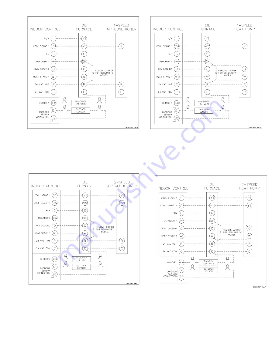
Fig. 5—24 VAC Oil Furnace Wiring with 1-Speed

Air Conditioner

Fig. 6—24 VAC Oil Furnace Wiring with 2-Speed

Air Conditioner

A04184

A04185

Fig. 7—24 VAC Oil Furnace Wiring with 1-Speed

Heat Pump

A04186

Fig. 8—24 VAC Oil Furnace Wiring with 2-Speed

Heat Pump

9

Summary of Contents for 58VLR

Page 1: ...4 Blower Removal 14 SAFETY CONSIDERATIONS FOR YOUR SAFETY DO NOT STORE OR USE GASOLINE OR OTHER FLAMMABLE VAPORS AND LIQUIDS IN THE VI CINITY OF THIS OR ANY OTHER APPLIANCE DO NOT ATTEMPT TO START THE BURNER WHEN EXCESS OIL HAS ACCUMULATED WHEN THE FURNACE IS FULL OF VAPOR OR WHEN THE COMBUSTION CHAMBER IS VERY HOT CARBON MONOXIDE POISONING FIRE EXPLOSION HAZARD Failure to follow this warning coul...

Page 2: ...le Ontario M9W 1R3 Recognize safety information This is the safety alert symbol When you see this symbol on the furnace and in instructions or manuals be alert to the potential for personal injury Understand the signal words DANGER WARNING and CAU TION These words are used with the safety alert symbol DAN GER identifies the most serious hazards which will result in severe personal injury or death ...

Page 3: ...d or drawing combustion products into the structure The furnace is controlled by a thermostat It may not be hot wired to provide heat continuously to the structure without thermostatic control Clean outside air is provided for combustion This is to minimize the corrosive effects of adhesives sealers and other construction materials It also prevents the entrainment of drywall dust into combustion a...

Page 4: ...e location should not interfere with proper circulation of air within the confined space See NFPA 31 Section 1 5 In addition to air needed for combustion process air shall be provided as required for cooling of equipment or material controlling dew point heating drying oxidation or dilution safety exhaust and odor control In addition to air needed for combustion air shall be supplied for ventilati...

Page 5: ...her within 12 in of floor Each opening must have a free area of at least 1 sq in per 1000 Btuh of total input rating but not less than 100 sq in Refer to Table 4 All Air From Outside the Structure If outside air is supplied to a confined space then the 2 openings must be equal and located as above 1 If combustion air is taken through a permanent opening directly communicating with the outdoors the...

Page 6: ...ation in chimney or vent If dete rioration is discovered chimney must be repaired or vent must be replaced 2 Inspection to ascertain that vent system is clear and free of obstructions Any blockage must be cleared before installing furnace 3 Cleaning chimney or vent if previously used for venting a solid fuel burning appliance or fireplace 4 Confirming that all unused chimney or vent connections ar...

Page 7: ... electrical connections in accordance with National Electrical Code NEC ANSI NFPA 70 2001 and any local codes or ordinances that might apply For Canadian installations all electrical connections must be made in accordance with Canadian Electrical Code CSA C22 1 or subauthorities having jurisdiction FIRE HAZARD Failure to follow this warning could result in serious injury death or property damage D...

Page 8: ...Fig 4 Wiring Diagram A04182 8 ...

Page 9: ...e Wiring with 1 Speed Air Conditioner Fig 6 24 VAC Oil Furnace Wiring with 2 Speed Air Conditioner A04184 A04185 Fig 7 24 VAC Oil Furnace Wiring with 1 Speed Heat Pump A04186 Fig 8 24 VAC Oil Furnace Wiring with 2 Speed Heat Pump 9 ...

Page 10: ...and vent for 10 seconds establishing the combustion air pattern During this time the solenoid valve holding oil pressure will be approximately 100 psig Solenoid valve opens allowing oil to flow through nozzle At the same time the burner motor s ignition coil produces spark 3 Spark ignites oil droplets 4 Cad cell senses flame and burner continues to fire Ignition transformer ceases sparking 5 After...

Page 11: ...When the thermostat is satisfied the furnace BLWM continues operating at 50 percent heating airflow for an additional 3 min 3 Opening only R Y Y2 circuit switches BLWM to heat pump low heat airflow DEFROST When furnace controls R to W W1 and Y Y2 circuits are closed furnace control CPU starts and burner and BLWM operation is at oil heating airflow during defrost Step 3 Combustion Check In order to...

Page 12: ...rities such as burning to 1 side or pulsating flame patterns should be corrected by changing nozzle Step 4 Fan Adjustment Check This furnace is equipped with a variable speed motor The blower is factory set to deliver the required airflow for 0 75GAL HR US INPUT and 3 0 tons air conditioning for the 58VLR105 See Tables 11A 11B and 11C The blower is factory set to deliver the required airflow for 0...

Page 13: ... R1 JW6 R3 D20 D1 D3 D04 D02 D13 R13 JW2 JW3 JW7 LED7 GRN R14 R12 D17 D18 D19 D21 D15 D16 LED4 LED3 LED5 LED7 LED8 LED1 GRN GRN GRN GRN GRN GRN P3 Y Y Y2 G DH O W R C HSC 1 1168 83 1 NOTES 1 The Red LED to the right of P 1 will illuminate whenever the limit switch is open 2 The Green LED below the left end of P 1 will flash when the blower motor is operating The LED will flash one time for each 10...

Page 14: ...any heat exchanger gaskets with new gaskets when any heat exchanger plates or covers are re moved could lead to heat exchanger leakage sooting and or a hazardous condition capable of causing personal injury or death This furnace should never be operated without an air filter Disposable filters should be replaced at least once a year If equipped to provide cooling filters should be replaced a minim...

Page 15: ...the CFM is reduced by 15 COOLING MODE OR HEAT PUMP HEATING MODE 2 SPEED LOW 24 VAC INPUT R TO G Y1 AND O FOR COOLING SW2 COOL Dip Switch Position A C Size TON CFM with SW3 ADJ Dip Switch A Position CFM with SW3 ADJ Dip Switch B Position CFM with SW3 ADJ Dip Switch C Position A 1 OFF 2 OFF 3 0 580 635 520 B 1 ON 2 OFF 2 5 480 530 435 C 1 OFF 2 ON 2 0 385 425 345 D 1 ON 2 ON 1 5 290 320 260 NOTE In ...

Page 16: ...D O FOR COOLING SW2 COOL Dip Switch Position A C Size TON CFM with SW3 ADJ Dip Switch A Position CFM with SW3 ADJ Dip Switch B Position CFM with SW3 ADJ Dip Switch C Position A 1 OFF 2 OFF 5 0 965 1060 865 B 1 ON 2 OFF 4 0 770 845 695 C 1 OFF 2 ON 3 5 675 740 605 D 1 ON 2 ON 3 0 580 635 520 NOTE In Cooling Dehumidification mode with no 24 VAC input to DH the CFM is reduced by 15 DELAY PROFILE FOR ...

Page 17: ...ct theory and skills programs is available using popular video based formats and materials All include video and or slides plus companion book Classroom ServiceTraining plus hands on the products in our labs can mean increased confidence that really pays dividends in faster troubleshooting fewer callbacks Course descriptions and schedules are in our catalog CALL FOR FREE CATALOG 1 800 644 5544 Pac...

Page 18: ...18 ...

Page 19: ...19 ...

Page 20: ...231 58vlr2si Manufacturer reserves the right to discontinue or change at any time specifications or designs without notice and without incurring obligations Book 1 4 Tab 6a 8a PC 101 Catalog No 535 80171 Printed in U S A Form 58VLR 2SI Pg 20 2 05 Replaces 58VLR 1SI ...

Reviews: