background image

Rev. (0) - 2012

Quality

Management System

ISO 9001 : 2008

Certificate No.: QS-5519HH

Enviromental 

Management System

ISO 14001 : 2004

Certificate No : 12 104 30334 TMS

Safety 

Management System

BS OHSAS 18001 : 2007

Certificate No : 12 116 30334 TMS

03502825

Carrier is committed to continuously improving its products according to national and international standards  

to ensure the highest quality and reliability standards, and to meet market regulations and requirements.  
All specifications subject to change without prior notice according to Carrier policy of continuous development.

 INSTALLATION MANUAL

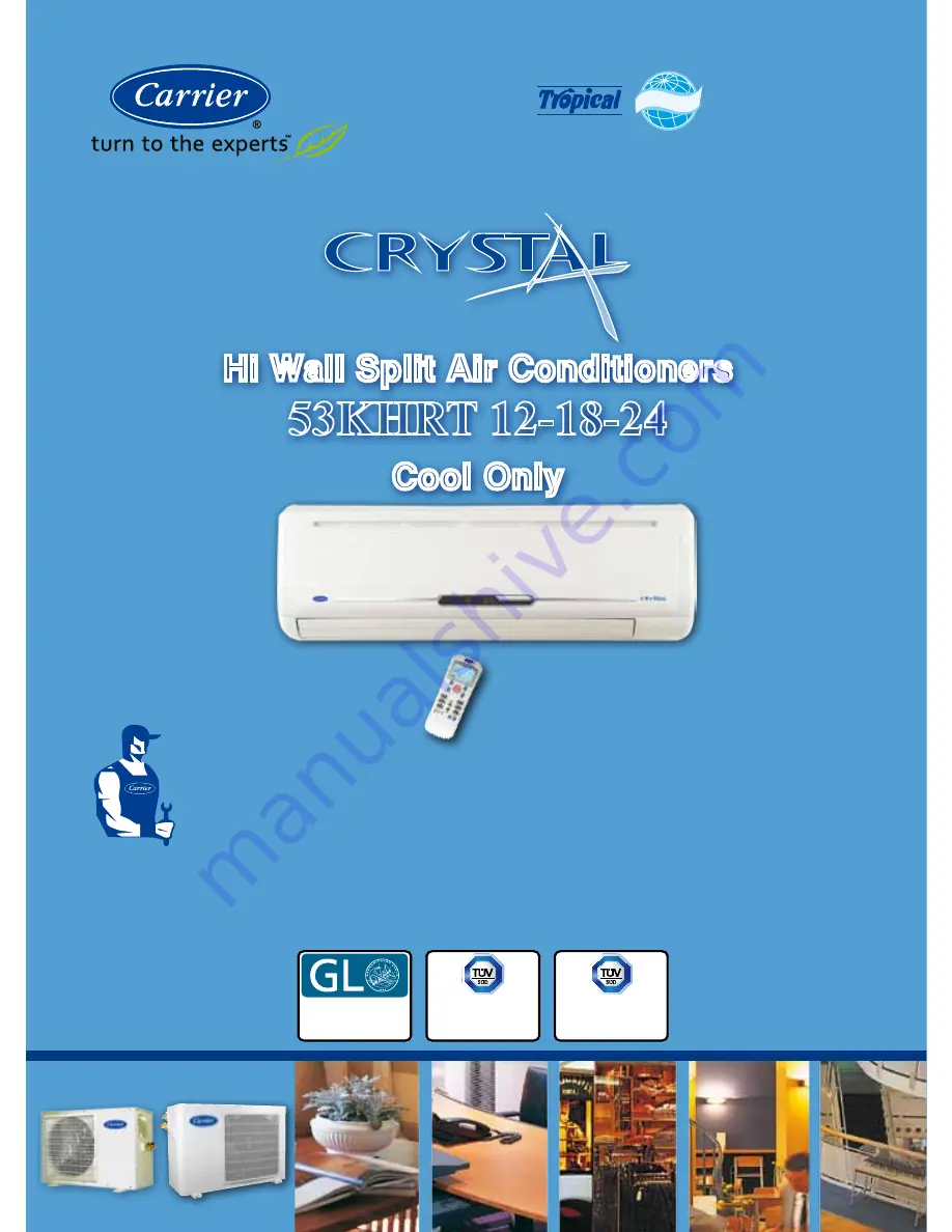
Hi Wall Split Air Conditioners

53KHRT 12-18-24

Cool Only

220-240V ~, 50Hz

R22

Summary of Contents for 53KHRT 12-18-24 Crystal

Page 1: ...03502825 Carrier is committed to continuously improving its products according to national and international standards to ensure the highest quality and reliability standards and to meet market regul...

Page 2: ...11 INSTALLTION ACCESSORIES 13 12 INSTALLATION CHART 15 13 INDOOR UNIT INSTALLATION 12 1 PREPARING UNIT BEFORE INSTALLATION 16 12 2 INSTALLATION STEPS 18 14 REMOTE CONTROL INSTALLATION 21 15 OUTDOOR UN...

Page 3: ...lectric drill Hole core drill 12 Hexagonal wrench 4mm 4 Measure tape 13 Torque wrench 5 Water level gauge 14 Vacuum pump 6 Pipe clamp 15 Gas leak detector 7 Pipe cutter 16 Gauge manifold 8 Spanner hal...

Page 4: ...ke the electrical connections Similarly when disassembling disconnect the electrical wiring first and only then open refrigerant connections What is not covered in our warranty 1 Failure due to wrong...

Page 5: ...ontal supply air louver 7 Vertical supply air louvers 8 Air filters 9 Manual control button 10 Power cord 11 Inter connecting refrigerant piping and electrical cables between indoor and outdoor units...

Page 6: ...ient 12 System Size 7 Nominal Power Supply 220 240V 50Hz 1Ph 0 Wireless Remote Control 8 Miraco Carrier 5 OPERATING LIMITS COOLING Difference Dry Bulb Temp C Wet Bulb Temp C Indoor temperature Maximum...

Page 7: ...C 42KHRT12 790 275 190 8 5 42KHRT18 940 275 198 12 42KHRT24 1030 313 221 17 7 DIMENSIONS AND WEIGHT OF OUTDOOR UNIT DIMENSIONS mm Model Mounting Dimensions mm Unit Dimensions mm Weight A B C D E 38KHR...

Page 8: ...vice and maintenance Select installation location so that the wall hole required to pass the outlet refrigerant piping lines electrical cables and condensate drain line from indoor unit can be in one...

Page 9: ...ns furn t may affe unit oid an insta vironment w oid an insta vironment a ves genera ders and m face to allo rry the unit n nt TION Con ation locat r air to all condition ation of the n ation locat di...

Page 10: ...oling performance Avoid installation location which can lead to excessive height difference between indoor and outdoor units to avoid alteration on system cooling performance Avoid installation locati...

Page 11: ...d installation location which is full of sulfuric gas which may result in malfunction Select installation location where the operation noise and discharged air are not disruptive to your neighbors Whe...

Page 12: ...side of outdoor unit should by away from any obstacle by 400 mm or more to ensure easy access to refrigerant and electrical connections The right side of outdoor unit air inlet should be away from an...

Page 13: ...l support to ensure free air circulation The left side of outdoor unit should by away from any obstacle by 400 mm or more to ensure easy access to refrigerant and electrical connections The right side...

Page 14: ...ower supply is close to the outdoor unit The installation location is close to the indoor unit The installation location is able to support operating weight of outdoor unit The installation location i...

Page 15: ...ping lines 11 2 STANDARD INSTALLATION ACCESSORIES SUPPLIED FROM THE FACTORY Only for export markets DESCREPTION SHAPE QTY USAGE Flare nuts 3 8 1 4 supplied with outdoor unit 38KHRT12 1 1 To be mounted...

Page 16: ...s and condensate drain line Finishing tape PVC film To tie together the refrigerant piping lines electrical connection cables and condensate drain line Vinyl tape To stick pipe insulation Drain hose I...

Page 17: ...cuum pump 2 Drilling hole thru the wall 6 Connecting condensate drain line 10 Refrigerant leak test 3 Installing indoor unit 7 Connecting electrical wiring 11 Opening service valves 4 Pipes flaring 8...

Page 18: ...t right side or from unit left side remove the pipe cover form the side panel Size 12K Size 18K Size 24K Right rear side refrigerant pipe hole 65 45 90 120 mm or more to wall Left rear side refrigeran...

Page 19: ...s th es e made as r hole make s o that the he f the hole is Sleeve For ckness of th e and cut PV e thickness o g Sleeve In ole a sleeve dth to be equ s drain hose ll hole Cont FORE INS Precaution lly...

Page 20: ...vibrations and sound during unit operation d Check that the wall hang bracket does not move This can cause noise during operation See chapter 18 Connecting Electrical Wiring Step 2 Electrical wiring o...

Page 21: ...move indoor unit from side to side to see that it is securely hooked 3 Piping can easily be made by lifting the indoor unit with a cushioning material between the indoor unit and the wall Get it out...

Page 22: ...ttery symbols indicated in batteries compartment NOTES 1 The remote control uses two alkaline batteries 1 5 Volts 2 Do not use old batteries or batteries of different types as this may cause the remot...

Page 23: ...he curtains to avoid direct sunlight 3 Avoid obstacles obstructions such as curtains doors or other materials between the remote control and the receiver of indoor unit to avoid blocking the signals f...

Page 24: ...and 2 sp 4 with right 5 and 2 sp with right s 5 and 4 sp r before mou with torque appearance wall rt 4 3 LATION EPS BEFO b Lift unit ON STEPS n Qt 1 1 1 2 8 8 y t side item1 pring washer t side item...

Page 25: ...23 16 CONNECTING REFRIGERANT PIPING LINES 16 1 REFRIGERANT CONNECTIONS CHART 1 Pipes Flaring 2 Pipes Connections 3 Air Purging 4 Leak Check 5 Pipes Insulation 6 Opening Valves...

Page 26: ...nt leak testing and to facilitate service and maintenance NOTES 1 For right side or left side piping remove the pipe cover from side panel Explain to the client that the pipe cover must be kept as it...

Page 27: ...ot bend the e place n extending ipe by unw ming the p pes flatteri mum radiu n 100 mm t T PIPING L height diff oor units difference t n on syste length of r door and o difference t n on syste number o...

Page 28: ...e is ed horizont gerant is fr and toward excessive cally since eturn to th d disconn nections af void refrige NG LINES a bend th d slides it a tube bend nsulation i excessive tally so tha rom the to d...

Page 29: ...t w VE INDOO qual 4 meter to facilitate parts meters more r to the indo HE SAME e at the gas ompressor t Ind 12 r Unit K tdoor Unit 2K 18K 27 ING LINE LINES rant piping efrigerant pip tance betwe OR U...

Page 30: ...h refrigerant piping lines of length 3 meters and with added 50 grams for air and moisture purge from the system 2 For refrigerant piping lines of length more than 3 meters add in the field 25 grams o...

Page 31: ...PIPING RIGERAN e valve to open c gas port ort to open FRIGERAN EFRIGERA PIPING LIN NG TOOL quired tools 4 2 3 1 oor Unit 29 Cont T CONNE close close NT CONNE ANT CONN NES LS s available b 5 5 3 7 8 CT...

Page 32: ...f edg g burrs at rant piping amer ortant and s good flare a the pipe en per scraps fa e Piping e ends of bo n slide a flar flare have the follo ssy and sm must not ha f uniform len sealing cap water f...

Page 33: ...tive plastic igerant pipin g protectiv d liquid co r unit ective plastic frigerant pip e protective ore being in flare nuts rant piping large nut ne ut small nu rant piping l g flare nut refrigerant L...

Page 34: ...the flare n que indicate damage the t tightening refrigerant l ening the tor ge the tube f refrigerant ONNECTI her ends of ctively with outdoor uni B C when lines to the f T PIPING TING REFR d piping...

Page 35: ...will have undesirable effects as indicated below Pressure in the system rises Operating current rises Cooling efficiency drops Moisture in the refrigerant circuit may freeze and block capillary tubing...

Page 36: ...rench to press the valve core pin discharge for three seconds and then wait for one minute 5 Use torque wrench to tighten the service port cap to a torque of 1 8 kg m 18 Nm 6 Set the 3 way gas valve t...

Page 37: ...urging procedure using vacuum pump 1 Connect the vacuum pump to the charge set s centre hose 2 Evacuate for approximately one hour Confirm that the gauge needle has moved toward 0 1 Mpa 76 cmHg vacuum...

Page 38: ...erate the system for 10 to 15 minutes 3 Stop operation and wait for 3 minutes then connect the charge set to the service port of the 3 way gas valve Connect the charge hose with the push pin to the ga...

Page 39: ...LATING REFRIGERANT PIPING LINES To conserve energy and prevent wet floors due to condensation the gas and liquid piping lines must be well insulated with a proper insulation material The thickness of...

Page 40: ...LET LOCATIONS OF CONDENSATE DRAIN LINE WITH REFRIGERANT PIPING LINES AND ELECTRICAL CABLES FROM THE INDOOR UNIT NOTES 1 For the left hand and right hand piping remove the pipe cover from the side pane...

Page 41: ...han ds TE DRAIN ONNECTIN hose to of water n 2 slope 39 N LINE Co NG CONDE 5 Avo 6 Avoi 7 Avoid syste must head evacu 8 Drain Check th into the the drain ont ENSATE D id forming a d forming a d connect...

Page 42: ...r conditioner a separate circuit breaker with its own overload should be installed on the electrical distribution box D Operation On Off Circuit Breaker The installation of two pole automatic circuit...

Page 43: ...xtension cables If extension cables are needed use terminal block C Electrical Connections a Electrical connections must be performed in compliance with national and local wiring codes and standards b...

Page 44: ...3 16 53KHRT18 52 220 240 8 9 1889 10 4 2255 11 2 2461 20 53KHRT24 82 220 240 11 7 2355 12 6 2827 14 2 3075 25 NOTES 1 Starting Current duration is usually less than 1 Second 2 Operating Conditions 35...

Page 45: ...S 53KHRT24 4 mm2 4 mm2 1 mm2 1 mm2 1 mm2 NOTES 1 Connect the power supply to the indoor unit and then get the power required for the outdoor unit from the indoor unit 2 All dotted lines to be fitted b...

Page 46: ...l the gap between the outside wall pipe hole and the piping with sealing wall sleeve wall cap and sealer so that rain and wind cannot enter e Adjust the vertical louvers of supply air for correct air...

Page 47: ...rposes Cooling test running function can be performed by using manual control button through the following steps 1 Open and left the front panel up to an angle until it remains fixed with a clicking s...

Page 48: ...volt and 27 C return air to indoor unit and high speed of indoor unit motor 20 3 STEPS OF COOLING TEST RUNNING for models 53KHRT18 53KHRT24 1 Move circuit breaker to ON position 2 Operate the system f...

Page 49: ...ION The air conditioner automatically adjusts the vertical supply air direction in accordance with the operating mode To set the vertical supply air direction Up Down Perform this function while the u...

Page 50: ...ioner is started immediately after it was stopped the horizontal louver might not move for approximately 10 seconds Open angle of the horizontal louver should not be set too small as cooling performan...

Page 51: ...refrigerant piping lines are tested for refrigerant leakage e The gas and liquid service valves in outdoor unit are open f The cap nuts for flare valves are properly tightened 22 4 CONDENSATE DRAIN LI...

Page 52: ...ion c There is no any abnormal noise or vibration from the indoor unit during operation d The wireless remote control operate Correctly e Each lamp on the indoor unit lights normally 22 8 CUSTOMER GUI...

Page 53: ...ally sto d the lamps ms Led Le X X ction Reas air disconn tion main supply b ner by using nit 51 R MALFUN C FUNCTIO cess of air c the indoor u ops the ope of the indoo ed Ret op Ind op X Out op Com cu...

Page 54: ...www miraco com eg...

Reviews: