


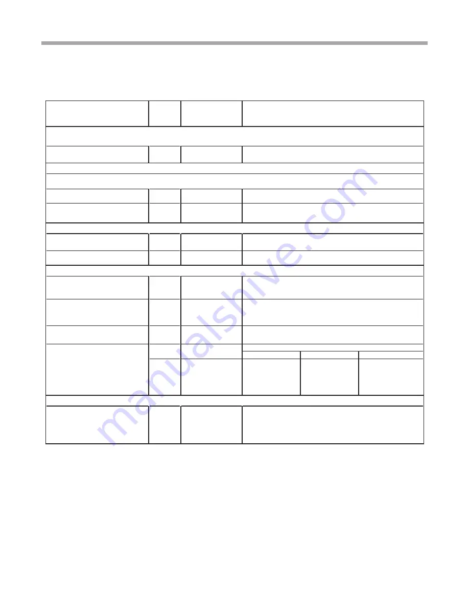
Water Quality Standards
Water Quality
Parameter
HX
Material
Closed
Recirculating
Open Loop and Recirculating Well
Scaling Potential - Primary Measurement
pH/Calcium Hardness
All
-
pH < 7.5 and Ca Hardness <100ppm
Method
Index Limits for Probable Scaling Situations -
(Operation outside these limits is not recommended)
Ryznar
All
-
6.0 - 7.5
Stability Index
If >7.5 minimize steel pipe use.
Langelier
All
-
-0.5 to +0.5
Saturation Index
If <-0.5 minimize steel pipe use. Based upon 150∞F [66∞C] HWG and
Direct well, 85∞F [29∞C] Indirect Well HX
Iron Fouling
Iron Fe
2+
(Ferrous)
All
-
<0.2 ppm (Ferrous)
(Bacterial Iron potential)
If Fe
2+
(ferrous)>0.2 ppm with pH 6 - 8, O2<5 ppm check for iron bacteria
Iron Fouling
All
-
<0.5 ppm of Oxygen
Above this level deposition will occur.
Corrosion Prevention
pH
All
6 - 8.5
6 - 8.5
Monitor/treat as
needed
Minimize steel pipe below 7 and no open tanks with pH <8
Hydrogen Sulfide (H
2
S)
All
-
<0.5 ppm
At H
2
S>0.2 ppm, avoid use of copper and copper nickel piping or HX's.
Rotten egg smell appears at 0.5 ppm level.
Copper alloy (bronze or brass) cast components are OK to <0.5 ppm.
Ammonia ion as hydroxide, chloride,
nitrate and sulfate compounds
All
-
<0.5 ppm
Maximum
Maximum Allowable at maximum water temperature.
Chloride Levels
50
°
F (10
°
C)
75
°
F (24
°
C)
100
°
F (38
°
C)
Copper
-
<20ppm
NR
NR
CuproNickel
-
<150 ppm
NR
NR
304 SS
-
<400 ppm
<250 ppm
<150 ppm
316 SS
-
<1000 ppm
<550 ppm
< 375 ppm
Titanium
-
>1000 ppm
>550 ppm
>375 ppm
Erosion and Clogging
Particulate Size and
Erosion
All
<10 ppm of particles
and a maximum
velocity of 6 fps [1.8 m/s].
Filtered for maximum
800 micron [800mm,
20 mesh] size.
<10 ppm (<1 ppm "sandfree" for reinjection) of particles and a maximum
velocity of 6 fps [1.8 m/s]. Filtered for maximum 800 micron [800mm,
20 mesh] size. Any particulate that is not removed can potentially
clog components.
Notes:
Rev.: 6/2/2010
• NR - Application not recommended.
• "-" No design Maximum.
• Closed Recirculating system is identified by a
closed pressurized piping system.
• Recirculating open wells should observe the open recirculating design considerations.
Above the given limits, scaling is likely to occur. Scaling indexes should be calculated using the limits below
Scaling indexes should be calculated at 150∞F [66∞C] for direct use and HWG applications, and at 90∞F [32∞C] for indirect HX use.
A monitoring plan should be implemented.
Table 3: Water Quality Standards
13
Wa t e r- t o - Wa t e r ( 5 0 Y E R ) S e r i e s - P u r o n
®
R e v. : 1 J u l y, 2 0 1 0


