19
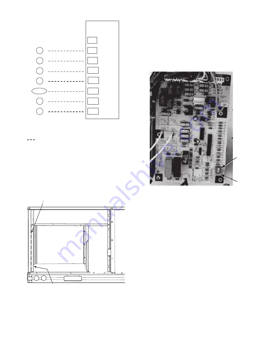
Fig. 27 — Typical Low-Voltage Control Connections
Thermostat Wiring, Units Without Thru-Base Connection Kit
Pass the thermostat control wires through the hole provided in
the corner post; then feed the wires through the raceway built
into the corner post to the control box. Pull the wires over to
the terminal strip on the upper-left corner of the Controls Con-
nection Board. See Fig. 28.
NOTE: If thru-the-bottom connections accessory is used, refer to
the accessory installation instructions for information on routing
power and control wiring.
Fig. 28 — Field Control Wiring Raceway
HEAT ANTICIPATOR SETTINGS
Set heat anticipator settings at 0.14 amp for the first stage and
0.14 amp for second-stage heating, when available.
COMMERCIAL DEFROST CONTROL
The Commercial Defrost Control Board (DFB) coordinates
thermostat demands for supply fan control, 1 or 2 stage cool-
ing, 2 stage heating, emergency heating and defrost control
with unit operating sequences. The DFB also provides an in-
door fan off delay feature (user selectable). See Fig. 29 for
board arrangement.
Fig. 29 — Defrost Control Board Arrangement
The DFB is located in the 50HCQ unit’s main control box (see
Fig. 30). All connections are factory-made through harnesses
to the unit’s CTB, to IFC (belt-drive motor) or to ECM (direct-
drive motor), reversing valve solenoids and to defrost thermo-
stats. Refer to Table 3 for details of DFB Inputs and Outputs.
Reversing valve control
The DFB has two outputs for unit reversing valve control. Op-
eration of the reversing valves is based on internal logic; this
application does not use an “O” or “B” signal to determine re-
versing valve position. Reversing valves are energized during
the cooling stages and the defrost cycle and de-energized
during heating cycles. Once energized at the start of a cooling
stage, the reversing valve will remain energized until the next
heating cycle demand is received. Once de-energized at the
start of a Heating cycle, the reversing valves will remain de-en-
ergized until the next cooling stage is initiated.
Compressor control
The DFB receives inputs indicating Stage 1 Cooling, Stage 2
Cooling and Stage 1 Heating from the space thermostat or unit
control system (PremierLink™ controller or RTU Open con-
troller); it generates commands to start compressors with or
without reversing valve operation to produce Stage 1 Cooling
(one compressor runs), Stage 2 Cooling (both compressors run)
or Stage 1 Heating (both compressors run).
X
C
G
W2
R
C
W2
G
W1
O/B/Y2
Y2
W1
R
Y1
Y1
Typic
a
l
Thermo
s
t
a
t
Connection
s
T
H
E
R
M
O
S
T
A
T
(Note 1)
(Note 2)
1. Typic
a
l m
u
lti-f
u
nction m
a
rking. Follow m
a
n
u
f
a
ct
u
rer’
s
config
u
r
a
tion
in
s
tr
u
ction
s
to
s
elect Y2. Do not config
u
re for O o
u
tp
u
t.
2. W2 connection not req
u
ired on
u
nit
s
witho
u
t electric he
a
ting.
Field Wiring
Centr
a
l
Termin
a
l
Bo
a
rd
Note
s
:
RACEWAY
HOLE IN END PANEL (HIDDEN)
DIP
Switches
Speed-Up
Jumpers
Summary of Contents for 50HCQD07
Page 4: ...4 Fig 2 Unit Dimensional Drawing 07 08 Size Units ...
Page 5: ...5 Fig 2 Unit Dimensional Drawing 07 08 Size Units cont ...
Page 6: ...6 Fig 3 Unit Dimensional Drawing 09 Size Units ...
Page 7: ...7 Fig 3 Unit Dimensional Drawing 09 Size Units cont ...
Page 24: ...24 Fig 37 Electro Mechanical Control Wiring 50HCQ A07 D07 208 230v 460v 575v ...
Page 25: ...25 Fig 38 Electro Mechanical Control Wiring 50HCQ D07 Tier 2 1 Compressor 208 230v 460v 575v ...
Page 26: ...26 Fig 39 Electro Mechanical Control Wiring 50HCQ 08 09 208 230v 460v 575v ...
Page 27: ...27 Fig 40 Electro Mechanical Power Wiring 50HCQ A07 D07 208 230v 460v 575v ...
Page 28: ...28 Fig 41 Electro Mechanical Power Wiring 50HCQ D07 Tier 2 1 Compressor 208 230v 460v 575v ...
Page 29: ...29 Fig 42 Electro Mechanical Power Wiring 50HCQ 08 09 208 230v 460v 575v ...
Page 30: ...30 Fig 43 PremierLink Wiring Schematic 50HCQ07 09 208 230v 460v 575v ...
Page 31: ...31 Fig 44 RTU Open System Control Wiring ...
Page 49: ......


