


12
5. Thoroughly apply Totaline environmentally balanced coil
cleaner solution to all coil surfaces including finned area,
tube sheets and coil headers.
6. Hold garden sprayer nozzle close to finned areas and apply
cleaner with a vertical, up-and-down motion. Avoid spraying
in horizontal pattern to minimize potential for fin damage.
7. Ensure cleaner thoroughly penetrates deep into finned
areas. Interior and exterior finned areas must be thor-
oughly cleaned. Finned surfaces should remain wet with
cleaning solution for 10 minutes. Ensure surfaces are not
allowed to dry before rinsing. Reapply cleaner as needed
to ensure 10-minute saturation is achieved.
8. Thoroughly rinse all surfaces with low velocity clean
water using downward rinsing motion of water spray noz-
zle. Protect fins from damage from the spray nozzle.
Evaporator Coil
Cleaning the Evaporator Coil
1. Turn unit power off. Install lockout tag. Remove evapora-
tor coil access panel.
2. If economizer or two-position damper is installed, remove
economizer by disconnecting Molex
1
plug and removing
mounting screws.
3. Slide filters out of unit.
4. Clean coil using a commercial coil cleaner or dishwasher
detergent in a pressurized spray canister. Wash both sides
of coil and flush with clean water. For best results, back-
flush toward return-air section to remove foreign material.
Flush condensate pan after completion.
5. Reinstall economizer and filters.
6. Reconnect wiring.
7. Replace access panels.
Evaporator Coil Metering Devices
Three different evaporator coil metering systems are used on
50FC sizes 04-07. 50FC 04-06 units without the Humidi-MiZ-
er
®
option use the Acutrol™ system for evaporator metering.
50FC 07 units with or without the Humidi-MiZer option use a
TXV-distributer system.
Check the unit’s information data plate for Position 6 value,
then compare this value to the Model Number Nomenclature
on page 54 to confirm the unit’s construction.
The metering devices are multiple fixed-bore devices (Acutrol)
swedged into the horizontal outlet tubes from the liquid header,
located at the entrance to each evaporator coil circuit path.
These are non-adjustable. Service requires replacing the entire
liquid header assembly.
To check for possible blockage of one or more of these meter-
ing devices, disconnect the supply fan contactor (IFC) coil,
then start the compressor and observe the frosting pattern on
the face of the evaporator coil. A frost pattern should develop
uniformly across the face of the coil starting at each horizontal
header tube. Failure to develop frost at an outlet tube can indi-
cate a plugged or missing orifice.
THERMOSTATIC EXPANSION VALVE (TXV)
All 50FC 04-06 units equipped with the Humidi-MiZer option
and all 50FC 07 units include TXV control. The TXV is a
bi-flow, bleed port expansion valve with an external equalizer.
The TXVs are specifically designed to operate with Puron
®
refrigerant. Use only factory-authorized TXVs.
TXV Operation
The TXV is a metering device that is used in air conditioning
and heat pump systems to adjust to the changing load
conditions by maintaining a preset superheat temperature at the
outlet of the evaporator coil.
The volume of refrigerant metered through the valve seat is
dependent upon the following:
1. Superheat temperature is sensed by cap tube sensing bulb
on suction tube at outlet of evaporator coil. This tempera-
ture is converted into pressure by refrigerant in the bulb
pushing downward on the diaphragm, which opens the
valve using the push rods.
2. The suction pressure at the outlet of the evaporator coil is
transferred through the external equalizer tube to the
underside of the diaphragm.
3. The pin is spring loaded, which exerts pressure on the
underside of the diaphragm. Therefore, the bulb pressure
works against the spring pressure and evaporator suction
pressure to open the valve. If the load increases, the tem-
perature increases at the bulb, which increases the pressure
on the top side of the diaphragm. This opens the valve and
increases the flow of refrigerant. The increased refrigerant
flow causes the leaving evaporator temperature to
decrease. This lowers the pressure on the diaphragm and
closes the pin. The refrigerant flow is effectively stabilized
to the load demand with negligible change in superheat.
Replacing TXV
1. Recover refrigerant.
2. Remove TXV support clamp using a
5
/
l6
-in. nut driver.
3. Remove TXV using a wrench and an additional wrench on
connections to prevent damage to tubing.
4. Remove equalizer tube from suction line of coil. Use file
or tubing cutter to cut brazed equalizer line approximately
2 inches above suction tube.
5. Remove bulb from vapor tube inside cabinet.
6. Install the new TXV using a wrench and an additional
wrench on connections to prevent damage to tubing while
attaching TXV to distributor.
7. Attach the equalizer tube to the suction line. If the coil has
a mechanical connection, then use a wrench and an addi-
tional wrench on connections to prevent damage. If the
coil has a brazed connection, use a file or a tubing cutter to
remove the mechanical flare nut from the equalizer line.
Then use a new coupling to braze the equalizer line to the
stub (previous equalizer line) in suction line.
8. Attach TXV bulb in the same location where the original
(in the sensing bulb indent) was when it was removed,
using the supplied bulb clamps. See Fig. 19 on page 13.
9. Route equalizer tube through suction connection opening
(large hole) in fitting panel and install fitting panel in place.
10. Sweat the inlet of TXV marked “IN” to the liquid line.
Avoid excessive heat which could damage the TXV valve.
Use quenching cloth when applying heat anywhere on
TXV.
1. Molex is a registered trademark of Molex, Inc.
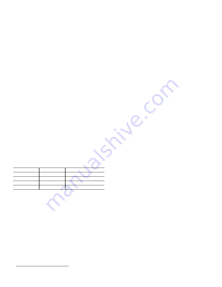
UNIT SIZE
HUMIDI-MIZER
EVAPORATOR METERING
04-06
NO
Acutrol
04-06
YES
Acutrol and TXV
07
NO
TXV
07
YES
TXV
Summary of Contents for 50FC A04 Series
Page 96: ...96 APPENDIX D WIRING DIAGRAMS Fig J 50FC 04 06 208 230 1 60 Unit with RTU Open Controller...
Page 97: ...97 APPENDIX D WIRING DIAGRAMS Fig K 50FC 04 06 208 230 3 60 Unit with RTU Open Controller...
Page 98: ...98 APPENDIX D WIRING DIAGRAMS Fig L 50FC 04 06 460 575 3 60 Unit with RTU Open Controller...
Page 99: ...99 APPENDIX D WIRING DIAGRAMS Fig M 50FC 07 208 230 Unit with RTU Open Controller...
Page 100: ...100 APPENDIX D WIRING DIAGRAMS Fig N 50FC 07 460 575 Unit with RTU Open Controller...
Page 101: ...101 APPENDIX D WIRING DIAGRAMS Fig O 50FC 04 06 Power Wiring Diagram 208 230 1 60...
Page 102: ...102 APPENDIX D WIRING DIAGRAMS Fig P 50FC 04 07 Power Wiring Diagram 208 230 3 60...
Page 103: ...103 APPENDIX D WIRING DIAGRAMS Fig Q 50FC 04 07 Power Wiring Diagram 460 575 3 60...
Page 104: ...104 APPENDIX D WIRING DIAGRAMS Fig R 50FC 04 06 SystemVu Control Wiring Diagram All Voltages...
Page 105: ...105 APPENDIX D WIRING DIAGRAMS Fig S 50FC 07 SystemVu Control Wiring Diagram All Voltages...
Page 106: ...106 APPENDIX D WIRING DIAGRAMS Fig T 50FC 04 06 SystemVu Power Wiring Diagram 208 230 1 60...
Page 107: ...107 APPENDIX D WIRING DIAGRAMS Fig U 50FC 04 07 SystemVu Power Wiring Diagram 208 230 3 60...
Page 108: ...108 APPENDIX D WIRING DIAGRAMS Fig V 50FC 04 07 SystemVu Power Wiring Diagram 460 575 3 60...