background image

19

LEAK TESTING
After  securing  the  connections,  test  the  system  for  any  leaks.

Always test hydronic systems with water as some components are

not designed to be inert gas pressurized.

Field  pressure  testing  for  leaks  should  not  exceed  300  psi  for

hydronic coil and valve package components. Consult factory if

higher limits are required.

REFRIGERANT COIL TESTING
Test refrigerant systems with dry nitrogen rather than air to pre

-

vent the introduction of moisture into the system. In the event that

leaking or defective components are discovered, notify the Sales

Representative BEFORE any repairs are attempted. All leaks must

be  repaired  before  proceeding  with  the  installation.  In  DX

systems, adequate freeze protection should be field-installed. Ex

-

ternal equalizer should be installed by others.
PIPING INSULATION
After system integrity has been established, insulate the piping in

accordance with the project specifications. This is the responsibili

-

ty of the installing or insulation contractor.
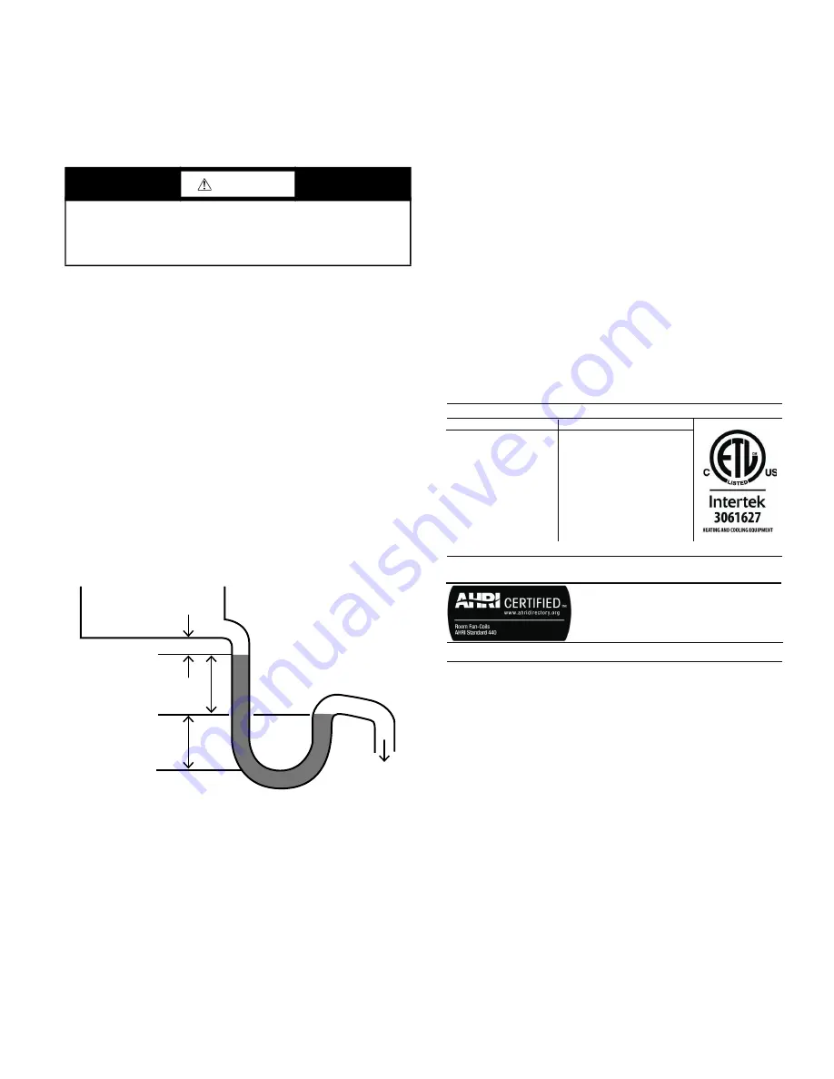
CONDENSATE DRAIN
Any fan coil unit with a drain pan is recommended to be equipped

with a drain trap to provide condensate drainage and prevent prop

-

erty damage.

The drain U-trap should be deep enough to offset maximum unit

static pressure difference as shown at Fig. 26, to prevent conden

-

sate flowing back to drain pan.

Fig. 26 — 

Condensate Drain U-Trap

CONDENSATE FLOAT SWITCH
The condensate float switch is used to detect clogged or restricted

condensate  pan drains. The condensate switch  uses a Normally

Closed contact to allow the system control power to pass through

the switch energizing the water valves and fans allowing normal

operation. When an overflow condition is detected by the switch,

it opens the NC contacts and de-energizes the water valves and

fans.

Step 4 — Make Electrical Connections

The unit serial plate lists the unit electrical characteristics includ

-

ing the required supply voltage, fan and heater amperage and re

-

quired circuit ampacity. (See Fig.  27.) The unit wiring diagram

displays all unit and field wiring. Every project is different and

each unit on a project may be different, the installer must be famil

-

iar with the wiring diagram and serial plate on the unit BEFORE

beginning any wiring.

Ensure all field electrical connections are in accordance with unit

wiring diagram and all  applicable national and local  code. The

type and size of all wiring and other electrical components includ

-

ing circuit breakers, disconnect switches, etc. shall be determined

by the individual job requirements. Verify conductor size is suit

-

able for the distance to the equipment connection and will support

the  equipment  electrical  load.  All  installations  including  field

wiring shall be made in compliance with all governing codes and

ordinances. Compliance with all codes is the responsibility of the

installing contractor.

All components furnished for field installation by either the facto

-

ry or the controls contractor shall be located and checked for prop

-

er function and compatibility. Inspect all internal components for

shipping damage. Inspect all electrical connections within the unit

control box and accessories and tighten if necessary.

NOTE:  All  field wiring  must  be  in accordance with governing

codes  and ordinances. Any modification  of unit wiring without

factory  authorization  will  invalidate  all  factory  warranties  and

nullify any agency listings. The manufacturer assumes no respon

-

sibility for any damages and/or injuries resulting from improper

field installation and/or wiring.

Fig. 27 — 

Serial Plate Example

CABINET/CONTROL BOX MAINTENANCE LIGHT
Optional Service Light provides a source of illumination in the

main unit cabinet and the control box during routine maintenance

and troubleshooting in the dark ceiling spaces. Light turns "ON"

when access panel or control box door is open, but unit is not pow

-

ered. (See Fig. 28.)

Step 5 — Connect Ductwork

All  ductwork  shall  be  installed  in  accordance  with  the  project

plans and specifications. See Fig. 22-25 for supply and return duct

flanges location and dimensions.

NOTE: When installing units that attach to branch duct piping, use

industry approved duct standards and configuration such as those

published by Air Conditioning Contractors of America (ACCA)

or American Society of Heating, Refrigeration and Air Condition

-

ing Engineers (ASHRAE). The standards provide necessary infor

-

mation on sizing, layout and installing supply and return air duct

systems. 

Flexible  duct  connections  should  be  used  on  all  air  handling

equipment. All ductwork and insulation shall be installed to allow

proper access to all components for service and repair such as fil

-

ters, motor/blower assemblies, etc.

CAUTION

Protect all water coils from freezing after initial filling with

water. Even if the system is drained, unit coils may still hold

enough water to cause damage when exposed to temperatures

below freezing.

Drain Pan

Safety Margin

TSP

TSP

To Drain

Max Water Coil Leaving Air or Max Motor AMB:

Max Fuse or Max Circ Breaker (HACR Type NEC):

Unit Intended for Indoor Use Only & Suited For 0.00 Clearance From Combustible Surfaces

-

25A - SCCR: 5KA

Unit Serial No:

Model No:

42DHA20

776004-60-1

 ELECTRICAL

 ENV/PERF

Motor(s):

Motor VPH:

Motor FLA:

Heater AMPS:

QTY of Motor(s):

Motor HP:

Min Circ Amps:

Heater VPH:

E020-71537402

277/1/60

5.10A

18.1A

5.0 kW

1

1 HP

29.0A

277/1/60

Max ESP:

Max Inlet Water Temp:

Coil Test:

High Side Coil Design:

Refrigerant Type:

1.65

300 PSIG

-

-

Max Outlet Air Temp:

Max Hot Water or Steam:

ARI Model:

Low Side Coil Design:

-

42DHA20

-

190F

2 PSIG

Heater Kw:

Motor Current:

5.10A

Manufactured in the USA

Summary of Contents for 42DH

Page 1: ...ns and have a fire extinguisher available Read these instructions thoroughly and follow all warnings or cautions attached to the unit Consult local building codes and appropriate national electrical c...

Page 2: ...ity for per sonal injury or property damage resulting from improper or unsafe practices during the handling installation service or operation of any equipment CAUTION Disconnect all power prior to any...

Page 3: ...confirm incoming and control power requirements match available power source Refer to unit nameplate and wiring diagram 1 Review all tags on unit to determine if shipping screws are to be removed Rem...

Page 4: ...rnished and Installed 5 8 Knockouts For Suspension rods 4 Places top and 4 places Bottom of unit Threaded rod suspension Field Furnished and installed Trapeze Recommended on Unit size 30 Minimum Recom...

Page 5: ...nces Top View 29 In Minimum Recommened Clearance 29 In Minimum Recommened Clearance 29 In Minimum Recommened Clearance Filter Piping Package For drain pan or coil removal the recommended clearance sho...

Page 6: ...ouble wall cabi net construction For a different coil and cabinet options use the weight correction factor table Table 1 Total Unit Weight Adjustment NOTES 1 Unit weights shown in pounds 10 are based...

Page 7: ...Fig 8 All hardware required for assembly is included and the base rails are letter coded for ease of assembly See Fig 9 Fig 8 Base Rails Fig 9 Letter Coding on Base Rail Parts PLACE UNIT ON THE BASE...

Page 8: ...mixing box with supplied No 8 x 1 2 in sheet metal screws two per side See Fig 12 For bottom entering configurations length adjustments to the bot tom damper shaft may need to be completed prior to fi...

Page 9: ...lter access panel See Fig 14 Fig 14 Optional Mixing Box 3 76 A C 2 4 61 4 102 H 2 4 61 3 76 1 25 2 51 2 51 W B Top Views BTM Rear Inlet 42DH Top Rear Inlet 42DH Top Front Inlet 42DV W 4 102 2 4 61 C 1...

Page 10: ...rence at any point during travel Tighten rod clamp of swivel onto each damper rod Fig 17 Install Damper 7 Confirm correct operation of dampers Adjust as needed Tighten remaining fasteners Step 3 Conne...

Page 11: ...5 1 2 0 625 1 2 0 625 16 22 1 1 125 1 1 125 1 1 125 1 1 125 1 2 0 625 30 1 1 2 1 625 1 1 2 1 625 1 1 2 1 625 1 1 2 1 625 1 2 1 625 HR CR CS HS Return Air Drain LH TELL TALE RH TELL TALE LEGEND 2 Verti...

Page 12: ...16 1 LH 10 5 8 7 3 4 12 9 5 8 7 RH 13 3 8 9 5 8 7 2 12 7 16 3 8 13 5 8 10 3 8 7 9 16 6 7 3 4 15 5 8 8 1 8 1 LH 10 5 8 7 3 4 12 11 13 16 9 3 16 RH 13 3 8 11 13 16 9 3 16 2 12 7 16 3 8 13 5 8 12 1 2 9 3...

Page 13: ...06 12 0 375 1 4 3 4 0 875 1 2 0 625 1 2 0 625 16 22 0 375 1 4 1 1 125 1 1 125 1 2 0 625 30 0 625 1 2 1 1 2 1 625 1 1 2 1 625 1 1 2 1 625 LEGEND HR HS SL LL Return Air Drain LH TELL TALE RH TELL TALE N...

Page 14: ...1 2 2 3 4 6 1 4 5 1 8 17 1 8 3 3 4 2 5 8 2 5 8 6 2 4 4 7 8 3 1 4 3 1 4 6 16 4 6 1 2 7 1 8 12 1 2 2 3 4 6 1 4 5 1 8 17 1 8 3 3 4 2 5 8 2 5 8 6 2 4 6 3 8 10 13 5 8 6 6 8 4 1 8 2 5 8 6 20 22 4 6 1 2 7 1...

Page 15: ...WIDTH HEIGHT SUPPLY DUCT RETURN DUCT MOUNTING HOLES AUX CTRL BOX M A B C D E F G J K L 06 9 x 6 36 28 19 3 4 8 7 8 10 7 8 13 3 4 2 1 4 24 1 4 14 2 3 4 27 1 4 35 1 4 5 3 4 2 08 9 x 6 36 28 19 3 4 8 7...

Page 16: ...tors and or cabinet lighting option not required with low voltage 0 10v controls UNIT SIZE FAN SIZE DEPTH UNIT DEPTH WIDTH HEIGHT SUPPLY DUCT RETURN DUCT MIX BOX MOUNTING HOLES AUX CTRL BOX M A B C D...

Page 17: ...g UNIT SIZE FAN SIZE DEPTH WIDTH HEIGHT SUPPLY DUCT FLANGE RETURN DUCT FLANGE AUX CTRL BOX UNIT SIDE TO DUCT FLANGE UNIT BOTTOM TO DUCT FLANGE A B C E F L M N 06 9 x 6 20 28 36 1 2 8 7 8 10 7 8 15 1 8...

Page 18: ...field installation of actuator Kit consists of 2 crank arms 2 swivels and either a 25 in sizes 06 16 or 34 in sizes 20 30 length of 5 16 in rod 10 Add 2 in if using a prefilter or 4 in filter UNIT SIZ...

Page 19: ...ld wiring shall be made in compliance with all governing codes and ordinances Compliance with all codes is the responsibility of the installing contractor All components furnished for field installati...

Page 20: ...sible before beginning any system balancing Cooling Heating System Prior to the water system start up and balancing flush the chilled hot water systems to clean out dirt and debris which may have coll...

Page 21: ...tronically Commutated Motors ECM constant speed brushless DC which are easily adjustable in the field for desired performance Motors are pre programmed for constant speed mode 1 2 HP and 1 HP motors h...

Page 22: ...low rates in a convenient place for future reference Before and during water system balancing conditions may exist due to incorrect system pressures which may result in noticeable water noise or undes...

Page 23: ...air through the coil fins from the leaving air face This should again be followed by vacuuming Units equipped with regularly replaced air filters will require less frequent coil cleaning Electric Res...

Page 24: ...ed main drain line by flow from tell tale connection Should algae and or bacteria growth become a concern con sult an air conditioning and refrigeration supply organization familiar with local conditi...

Page 25: ...Detail Y Detail Y Filter Support Angle Bracket Filter Support Angle Bracket 1 Filter Slot 2 Filter Slot D See Detail Y See Detail X Detail X Detail Y Magnets C 2 Filter 1 Filter 4 Filter B A D 2 Filt...

Page 26: ...h Control Board Fig B No Electric Heat Three Phase Power with Control Board WARNING Wiring diagrams are provided as an example only ALWAYS refer to WIRING DIAGRAM attached to the unit WARNING Wiring d...

Page 27: ...WIRING DIAGRAM EXAMPLES cont Fig C Single Element Heater Single Stage Heat Single Phase Power with Control Board WARNING Wiring diagrams are pro vided as an example only ALWAYS refer to WIRING DIAGRAM...

Page 28: ...28 Fig D Two Element Heater Single Stage Heat Single Phase Power with Control Board WARNING Wiring diagrams are provided as an example only ALWAYS refer to WIRING DIAGRAM attached to the unit...

Page 29: ...CAL WIRING DIAGRAM EXAMPLES cont Fig E Two Element Heater Two Stage Heat Single Phase Power with Control Board WARNING Wiring diagrams are provided as an example only ALWAYS refer to WIRING DIAGRAM at...

Page 30: ...30 Fig F Three Element Heater Single Stage Heat Three Phase Power with Control Board WARNING Wiring diagrams are provided as an example only ALWAYS refer to WIRING DIAGRAM attached to the unit...

Page 31: ...AL WIRING DIAGRAM EXAMPLES cont Fig G Six Element Heater Single Stage Heat Three Phase Power with Control Board WARNING Wiring diagrams are provided as an example only ALWAYS refer to WIRING DIAGRAM a...

Page 32: ...32 Fig H Six Element Heater Two Stage Heat Three Phase Power with Control Board WARNING Wiring diagrams are provided as an example only ALWAYS refer to WIRING DIAGRAM attached to the unit...

Page 33: ...L WIRING DIAGRAM EXAMPLES cont Fig I Nine Element Heater Single Stage Heat Three Phase Power with Control Board WARNING Wiring diagrams are provided as an example only ALWAYS refer to WIRING DIAGRAM a...

Page 34: ...34 Fig J Nine Element Heater Two Stage Heat Three Phase Power with Control Board WARNING Wiring diagrams are provided as an example only ALWAYS refer to WIRING DIAGRAM attached to the unit...

Page 35: ...Power with Control Board Fig L No Electric Heat Single Phase Power without Control Board WARNING Wiring diagrams are provided as an example only ALWAYS refer to WIRING DIAGRAM attached to the unit WA...

Page 36: ...Board Fig N Single Element Heater Single Stage Heat Single Phase Power without Control Board WARNING Wiring diagrams are provided as an example only ALWAYS refer to WIRING DIAGRAM attached to the unit...

Page 37: ...L WIRING DIAGRAM EXAMPLES cont Fig O Two Element Heater Two Stage Heat Single Phase Power without Control Board WARNING Wiring diagrams are provided as an example only ALWAYS refer to WIRING DIAGRAM a...

Page 38: ...38 Fig P Three Element Heater Single Stage Heat Three Phase Power without Control Board WARNING Wiring diagrams are provided as an example only ALWAYS refer to WIRING DIAGRAM attached to the unit...

Page 39: ...WIRING DIAGRAM EXAMPLES cont Fig Q Six Element Heater Single Stage Heat Three Phase Power without Control Board WARNING Wiring diagrams are provided as an example only ALWAYS refer to WIRING DIAGRAM...

Page 40: ...40 Fig R Six Element Heater Two Stage Heat Three Phase Power without Control Board WARNING Wiring diagrams are provided as an example only ALWAYS refer to WIRING DIAGRAM attached to the unit...

Page 41: ...WIRING DIAGRAM EXAMPLES cont Fig S Nine Element Heater Single Stage Heat Three Phase Power without Control Board WARNING Wiring diagrams are provided as an example only ALWAYS refer to WIRING DIAGRAM...

Page 42: ...42 Fig T Nine Element Heater Two Stage Heat Three Phase Power without Control Board WARNING Wiring diagrams are provided as an example only ALWAYS refer to WIRING DIAGRAM attached to the unit...

Page 43: ...WIRING DIAGRAM EXAMPLES cont Fig U Nine Element Heater Three Stage Heat Three Phase Power without Control Board WARNING Wiring diagrams are provided as an example only ALWAYS refer to WIRING DIAGRAM...

Page 44: ......

Page 45: ......

Page 46: ...the right to discontinue or change at any time specifications or designs without notice and without incurring obligations Catalog No 04 53420022 01 Printed in U S A Form 42DHV 2SI Pg 46 1 22 Replaces...

Page 47: ...Y N __________ ARE FURNISH ONLY PARTSACCOUNTED FOR Y N __________ IS THE UNIT ARRANGEMENT HAND CORRECT Y N __________ IS THE UNIT STRUCTURAL SUPPORT COMPLETEAND CORRECT Y N __________ Handling and Ins...

Page 48: ...YTRAP IS DEEP ENOUGH __________ PRIME THE TRAPWITH WATER __________ CHECK SUPPLYAND RETURN WATER CONNECTIONS FOR LEAKS __________ FILL SYSTEMS WITH WATER REFRIGERANT __________ OPENAIR VENT ON TOP OF...

Reviews: