background image

20

Fig. 32 —Fan Disassembly 036-054

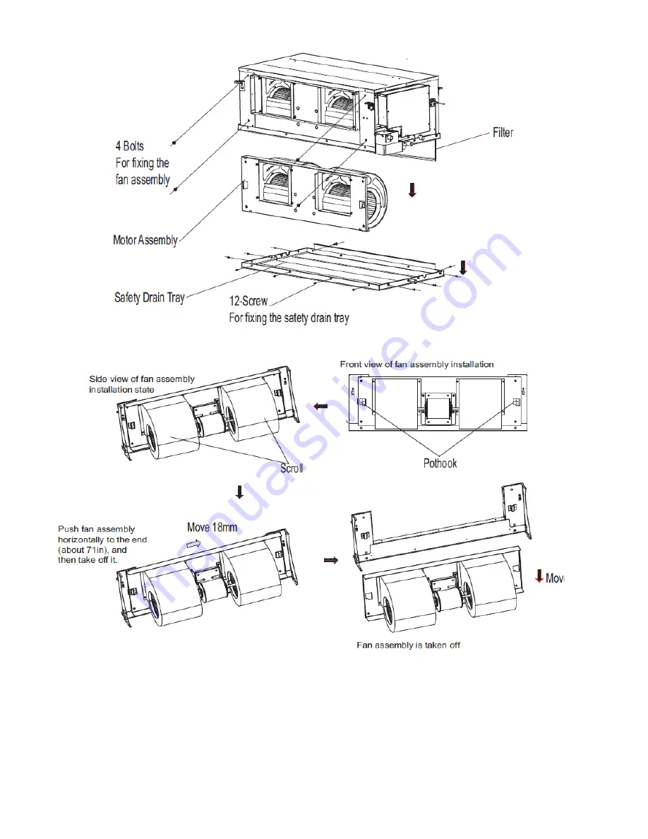
Fig. 33 —Fan Disassembly 036-054

1. Remove all 12 screws from the Safety Drain Tray, and remove the safety drain tray as shown in Fig. 32.
2. Remove all four bolts from the fan assembly as shown in Fig. 33.
3. Horizontally push fan assembly until it cannot not move any further.
4. Lift up slightly and take down to remove as shown in Fig. 33.
5. After the motor maintenance is complete, reinstall the fan assemblies, and connect the motor with electric control box.

Summary of Contents for 40VMA Series

Page 1: ...ert symbol When this symbol is displayed on the unit and in instructions or manuals be alert to the potential for personal injury WARNING Electrical shock can cause personal injury and death Shut off...

Page 2: ...size Figures 2 3 and 4 show the unit s dimensions Fig 4 Fig 8 shows fan performance curves Fig 1 Model Number Nomenclature Table 1 Components Shipped with Unit LEGEND VRF Variable refrigerant Flow NAM...

Page 3: ...Low 43 8 43 4 43 9 48 5 47 7 Medium 47 8 47 8 47 8 50 0 50 8 High 49 5 50 4 51 4 52 1 53 5 UNIT Unit Dimensions W x H x D in 51 3 16 X16 1 2 X27 3 16 56 11 16 X20 X36 3 8 Packing Dimensions W x H x D...

Page 4: ...4 DIMENSIONS Fig 2 40VMA036 054 Dimensions NOTE All dimensions are shown in inches...

Page 5: ...5 DIMENSIONS CONT Fig 3 40VMA072 096 Dimensions NOTE All dimensions are shown in inches...

Page 6: ...W G Upper Lim it of ESP 0 44 in W G Upper Limit of ESP 0 2 in WG Lower Limit of ESP 0 44 in WG Lower Limit of ESP 0 2 in WG ESP Fan Speed Range of Available Airflow Rate in H Speed Max Point Rating P...

Page 7: ...in WG H Speed M Speed L Speed H Speed M Speed L Speed H Speed M Speed L Speed ESP Fan Speed Range of Available Airflow Rate in H Speed Max Point Rating Point Min Point Max CFM SP in Mid CFM SP in Min...

Page 8: ...nit mounting point locations The unit must always be properly supported Temporary supports used during installation or service must be adequate to hold the unit securely To maintain warranty protect u...

Page 9: ...t should be installed in a position that is suitable to support the total weight of the unit refrigerant piping and condensate Proper access should be provided for maintenance for refrigerant piping E...

Page 10: ...t as possible See Fig 14 Condensate piping should slope downward in the direction of condensate flow with a minimum gradient of 1 inch per 100 inches See Fig 15 Fig 14 Condensate Piping When multiple...

Page 11: ...damage to or failure of units caused by incorrect wiring or voltage is not covered by the warranty Electric wiring must be sized to carry the full load amp draw of the motor starter and any other con...

Page 12: ...T2B Outlet Pipe Temperature Sensor XP1 8 Connectors XS1 4 Connector XT1 2 Terminal Block Optional Component or Field Wiring SW8 3GOT HUGXJ CN3 CN18 CN24 CN11 CN5 CN52 CN54 CN12 CN15 CN9 CN26 CN8 EARTH...

Page 13: ...XS1 4 Connector XT1 2 Terminal Block Optional Component or Field Wiring SW8 3GOT HUGXJ CN3 CN18 CN24 CN11 CN5 CN52 CN54 CN12 CN15 CN9 CN26 CN8 EARTH 7 BLUE 7 WHITE 7 7 RED Display board To wired contr...

Page 14: ...rs should be installed in a position that maintains good temperature control Position the thermostat approximately 48 inches above floor level Do not position thermostat where it can be directly affec...

Page 15: ...connect the indoor unit side of the communication wires using the connector provided with the accessories as shown in Fig 26 See Fig 27 and 28 for typical communication wiring of the heat pump and he...

Page 16: ...RRU 7R 6XE 0 7R RXWGRRU L1 L2 L3 L3 L3 L3 L4 L4 L5 L6 L7 L8 L9 L10 L11 Indoor unit 1 Indoor unit 2 Indoor unit 3 Indoor unit 4 Indoor unit 5 Indoor unit 6 wired controller Maximum wiring length L1 L2...

Page 17: ...0 L11 L3 L3 L3 L3 Indoor unit 1 Indoor unit 2 Indoor unit 3 Indoor unit 4 Indoor unit 5 Indoor unit 6 Maximun wiring length IW RUH 6WUDQGHG 6KLHOG IW RUH 6WUDQGHG 6KLHOG IW RUH 6WUDQGHG 6KLHOG IW RUH...

Page 18: ...ration is normal if applicable e No abnormal vibration or noise is noticed 3 While the system is in operation check the following on the outdoor unit a No abnormal vibration or noise is noticed b Cond...

Page 19: ...vides an example of the unit 1 Remove the 12 screws from the fixed Safety Drain Tray and take off the tray as shown in Fig 31 2 Take off the tray along the direction of the arrow as shown in Fig 31 3...

Page 20: ...n tray as shown in Fig 32 2 Remove all four bolts from the fan assembly as shown in Fig 33 3 Horizontally push fan assembly until it cannot not move any further 4 Lift up slightly and take down to rem...

Page 21: ...ule In addition Ensure all the electrical connections are secure Check the condensate pump operation if applicable Check the heating and cooling action to confirm proper operation INDOOR UNIT ADDRESSI...

Page 22: ...nd hold LOCK for at least ten seconds and press to query the address Programmable Controller 40VM900003 When setting an address connect only one wired controller to an indoor unit 1 Press FAN and BACK...

Page 23: ...ystem Defrost OFF Operation Light ON Only FAN dd None Heating Cooling Mode Conflict E1 Communication Error Between Indoor and Outdoor Unit E2 Check Indoor Ambient Temperature Sensor T1 E3 Check Room T...

Page 24: ...d fault Replace PC board E9 Communication Error Between Indoor Unit and Controller Signal wires are short circuited or disconnected Check or reconnect signal wires Signal wires close to electromagneti...

Page 25: ...atalog No 20 40VMA001 01 Printed in U S A Form 40VMA 2SI Pg 25 2 20 Replaces 40VMA 1SI Carrier Corporation 2020 APPENDIX A DIP SWITCH SETTINGS There are two DIP switches on the main board Figures A an...

Reviews: