


36
IPM Continuity Check
Turn off the power, let the large capacity electrolytic capacitors discharge completely, and dismount the IPM. Use a digital tester to measure
the resistance between P and UVWN; UVW and N.
Table 16— IPM Continuity Check
Digital Tester
Normal Resistance value
Digital Tester
Normal Resistance Value
(+) Red
(-) Black
∞
(
Several M W)
(+) Red
(-) Black
∞
(
Several M W)
P
N
U
N
U
V
V
W
W
(+) Red
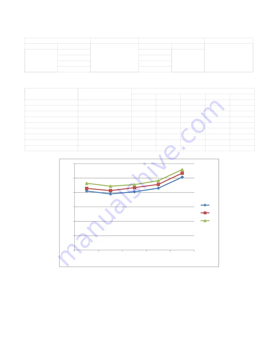
Pressure on Service Port
Table 17—Cooling Chart
_
F
_
C
Indoor Temp.
Outdoor Temp.
75 (23.89)
85 (29.44)
95 (35)
105 (40.56)
115 (46.11)
BAR
70
8.2
7.8
8.1
8.6
10.1
BAR
75
8.6
8.3
8.7
9.1
10.7
BAR
80
9.3
8.9
9.1
9.6
11.2
PSI
70
119
113
117
125
147
PSI
75
124
120
126
132
155
PSI
80
135
129
132
140
162
MPA
70
0.82
0.78
0.81
0.86
1.01
MPA
75
0.86
0.83
0.87
0.91
1.07
MPA
80
0.93
0.89
0.91
0.96
1.12
0.0
2.0
4.0
6.0
8.0
10.0
12.0
75
㸦
23.89
㸧
85
㸦
29.44
㸧
95
㸦
35
㸧
105
㸦
40.56
㸧
115
㸦
46.11
㸧
70
75
80
Pressure (bar)
Outdoor temp.
Fig. 45 – Pressure Bar


