


5
INSTALLATION
Step 1 — Unpack and Inspect Units —
Units are
packaged for shipment to avoid damage during normal transit
and handling. It is the receiving party’s responsibility to inspect
the equipment upon arrival. Any obvious damage to the carton
and/or its contents should be reported on the bill of lading and a
claim should be filed with the transportation company and the
factory. Unit should always be stored in a dry place, and in the
proper orientation as marked on the carton.
After determining the condition of the carton exterior, care-
fully remove each unit from the carton and inspect for hidden
damage. Check to make sure that items such as thermostats,
controller etc. are accounted for whether packaged separately
or shipped at a later date. Any hidden damage should be re-
corded, a claim should be filed with the transportation compa-
ny, and the factory should be notified. In the event a claim for
shipping damage is filed, the unit, shipping carton, and all
packing must be retained for physical inspection by the trans-
portation company. All units should be stored in the factory
shipping carton with internal packaging in place until installa-
tion.
PROTECTING UNITS FROM DAMAGE — Do not apply
force or pressure to the coil, piping, or drain stub-outs during
handling. All units should be handled by the chassis or as close
as possible to the unit mounting point locations.
The unit must always be properly supported. Temporary
supports used during installation or service must be adequate to
hold the unit securely. To maintain warranty, protect units
against hostile environments (such as rain, snow or extreme
temperature), theft, vandalism, and debris on jobsite. Do not al-
low foreign material to fall into drain pan. Prevent dust and de-
bris from being deposited on motor, fan wheels and coils. Fail-
ure to do so may have serious adverse effects on unit operation
and in the case of motor and blower assembly, may result in
immediate or premature failure. Failure of any unit caused by
deposits of foreign material on the motor or blower wheels will
not be covered by the manufacturer’s warranty. Some units
and/or job conditions may require some form of temporary
covering during construction.
PREPARING JOBSITE FOR UNIT INSTALLATION —
To save time and to reduce the possibility of costly errors, set
up a complete sample installation in a typical location at job-
site. Check all critical dimensions such as pipe, wire, and duct
connections requirements. Refer to job drawings and product
dimension drawings as required. Instruct all trades in their
parts of the installation. Units must be installed in compliance
with all applicable local code requirements.
IDENTIFYING AND PREPARING UNITS — Be
sure
power requirements match available power source. Refer to
unit nameplate and wiring diagram. In addition:
• Check all tags on unit to determine if shipping screws are
to be removed. Remove screws as directed.
• Rotate the fan wheel by hand to ensure that the fan is
unrestricted and can rotate freely. Check for shipping
damage and fan obstructions. Adjust blower motor as
required.
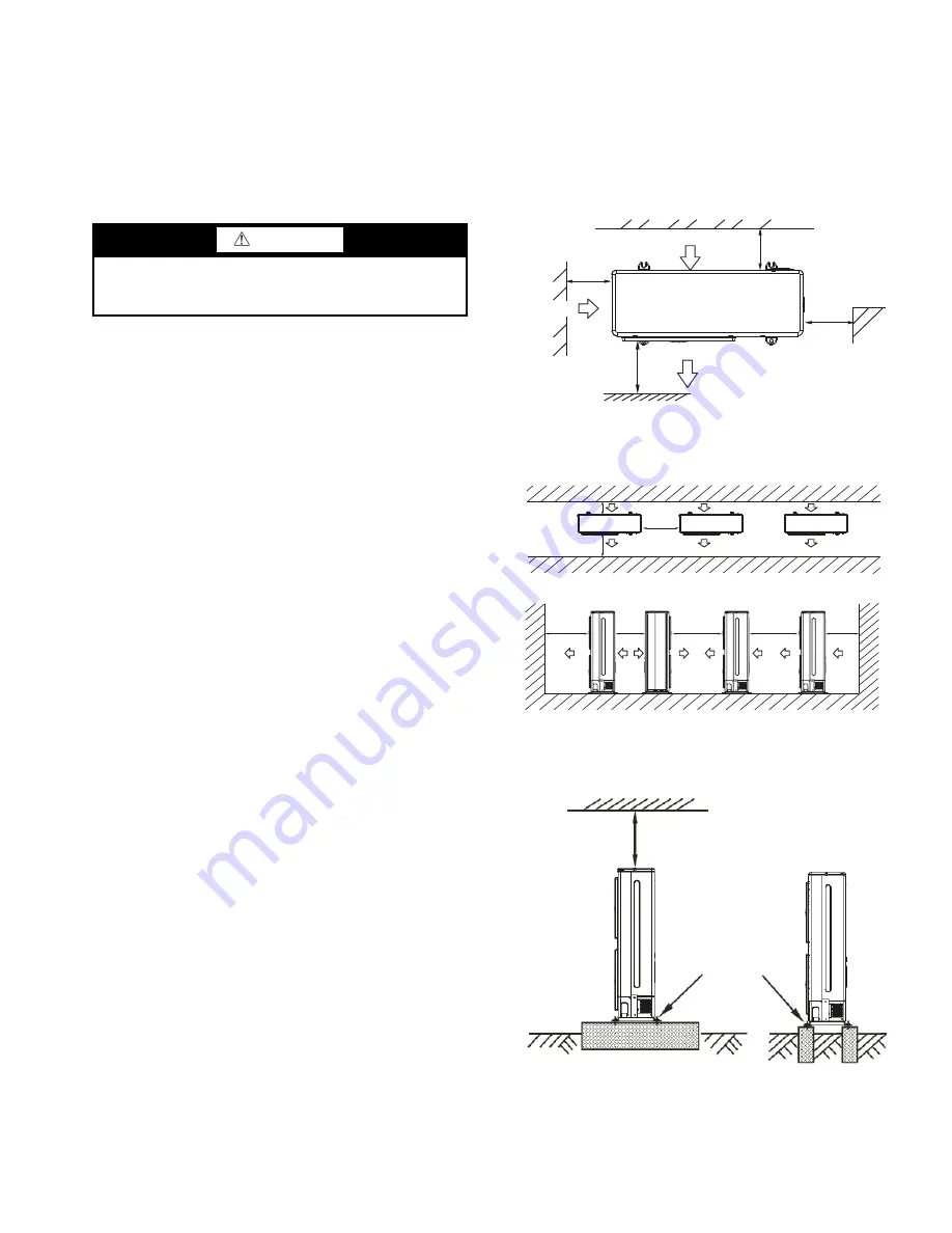
Step 2 — Position the Unit —
Units are suitable for
outdoor use only. For single unit installation, see Fig. 3. For
multiple or parallel unit installation, see Fig. 4. Unit should be
mounted on concrete and fastened to anchor bolts to prevent
the unit from tipping. See Fig. 5 for mounting details. Units in-
stalled in areas that are exposed to ambient temperatures below
freezing (32 F) should be installed on a snow/ice stand as de-
fined by local codes.
CAUTION
To avoid equipment damage, do not lift unit by the drain
pipe or refrigerant piping. Unit should be lifted using the
mounting brackets.
>11.8
>23.6
>
11
.8
>
78.7
WALL OR OBSTACLE
AIR INLET
AIR INLET
AIR OUTLET
MAINTAIN
CHANNEL
NOTE: ALL DIMENSIONS SHOWN IN INCHES.
A38-7435
Fig. 3 — Single Unit Installation
>78.7
>19.7
>118.1
>118.1
>11.8
>23.6
>78.7
>11.8
NOTE: ALL DIMENSIONS SHOWN IN INCHES.
A38-7436
Fig. 4 — Multiple or Parallel Unit Installation
FIX WITH BOLT
> 2
3
.6 in.
a38-7432
Fig. 5 — Mounting Unit on Concrete


