background image

14

Unit Settings

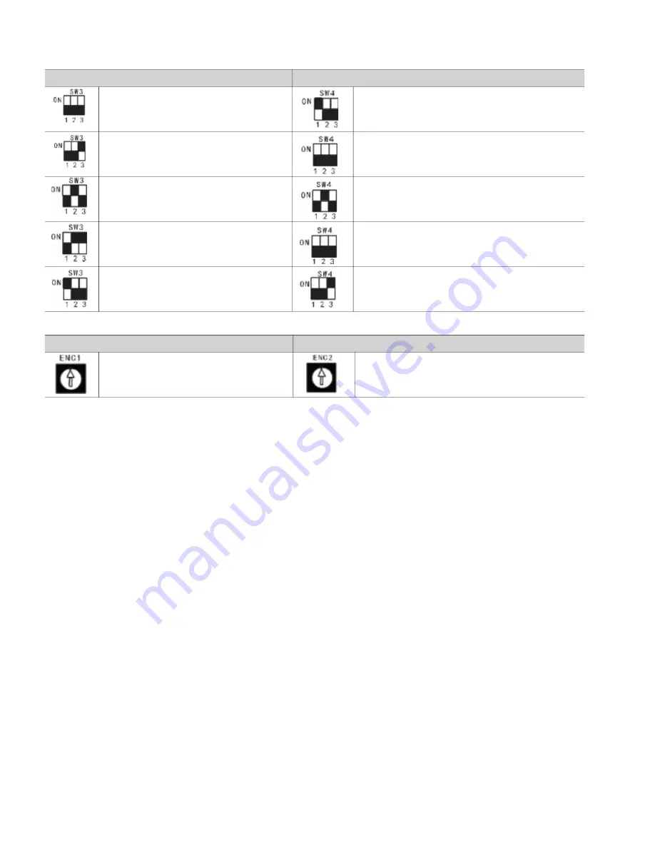
Table 11: SW3 and SW4 Function Definition

Table 12: ENC1 and ENC2

SW3 Function Definition

SW4 Function Definition

Heating priority mode

Automatic addressing

Cooling priority mode

Non-automatic addressing (factory default)

First running priority mode

Clear IDU address

Heating mode only

Fahrenheit temperature (factory default)

Cooling mode only

Celsius temperature

ENC1 Function Definition (factory use only)

ENC2 Function Definition

For factory use only

ODU network address dial-up

Only 0-7 used

Summary of Contents for 38VMA036HDS3-1

Page 1: ...and follow all warnings or cautions included in literature and attached to the unit Consult local building codes and the current editions of the National Electrical Code NEC ANSI NFPA American National Standards Institute National Fire Protection Association 70 In Canada refer to the current editions of the Canadian Electrical Code CSA Canadian Standards Association C22 1 Understand the signal wor...

Page 2: ...omponent The system contains oil and refrigerant under pressure To remove a component wear protective gloves and goggles and proceed as follows a Shut off electrical power to unit b Recover refrigerant to relieve all pressure from the system using both high pressure and low pressure ports c Traces of vapor should be displaced with nitrogen and the work area should be well ventilated Refrigerant in...

Page 3: ...0 Rated kBtu h 36 48 60 HEATING CAPACITY WITH NON DUCTED DUCTED INDOOR UNITS Nominal kBtu h 40 52 5 66 Rated kBtu h 40 52 5 66 ELECTRICAL CHARACTERISTICS WITH NON DUCTED INDOOR UNITS Cooling Power Consumption kW 3 10 4 60 6 10 EER Btu Wh 12 10 11 00 9 50 SEER Btu Wh 19 20 19 20 18 60 Heating Power Consumption kW 3 10 4 30 5 80 COP W W 3 62 3 42 3 19 HSPF Btu Wh 9 20 9 20 10 00 ELECTRICAL CHARACTER...

Page 4: ...ainst hostile environments theft vandalism and debris on jobsite Do not allow foreign material to fall into unit Failure to do so may have serious adverse effects on unit operation Failure of any unit caused by deposits of foreign material inside unit will not be covered by manufacturer s warranty Some units and or job conditions may require some form of temporary covering during construction PREP...

Page 5: ... Create an outlet near the base for drainage Refer to Fig 7 below for main drain connection Fig 7 Drain Connections Ensure the roof can handle the unit weight if mounted on the roof Step 3 Connect Refrigerant Piping and Wiring Refrigerant pipe connections are made on the side of the unit Remove the L shaped metal plate and route piping through the exposed opening Route power and control wiring thr...

Page 6: ...tions Use pipe adapter Components Shipped with Unit Page 2 when main pipe diameter for suction line is 5 8 inch CAUTION During brazing keep nitrogen in pipes to avoid oxidation inside the pipes Use soapy water or refrigerant leak detector to verify every joint in the refrigeration piping Fig 8 Piping and Control Wiring Connections Fig 9 Piping and Control Wiring Locations 38VMH UNIT CAPACITY tons ...

Page 7: ...or correct positioning of the joint Fig 12 Correct Branch Joint Positioning Install the branch joints properly to avoid oil accumulating in the system DESCRIPTION ALLOWABLE VALUE ft PIPES Piping Length Total Pipe Length 492 L1 L2 L3 L4 L5 L6 A B C D E Maximum Piping Length L Actual Length 296 L1 L3 L4 L5 L6 E Equivalent Length 328 First Branch to Farthest Indoor Unit 131 L3 L4 L5 L6 E Height Diffe...

Page 8: ...e and carefully re lease liquid refrigerant into the suction service port If the total calculated charge amount is added completely to the system the charging process is finished Step 6 Complete Electrical Connections See Fig 14 for a diagram of the unit s internal power and control wiring PIPE SIZE ON LIQUID SIDE in REFRIGERANT TO BE ADDED PER FOOT lb ft 1 4 0 015 3 8 0 040 1 2 0 080 5 8 0 120 3 ...

Page 9: ...9 Fig 14 Typical Wiring Diagram ...

Page 10: ...rce Power entry is on the right side of the unit when facing the fan grille or front of the unit Terminals for field power supply are suitable for copper conductors See Fig 15 and 16 for power wiring Main Power Bring wires from the disconnect switch through the knockout hole at the bottom right corner of the unit to the control box CAUTION Operating the unit on improper supply voltage or with exce...

Page 11: ...mes from the control board in the outdoor unit and does NOT require a separate source Use of 2 core stranded shielded cable is required Shield is used to protect the signal from interference The control wire between outdoor and indoor units is bus type See Fig 19 for communication wiring COMMUNICATION WIRING Communication wire must be wired as shown in Fig 8 and 19 Do not route communication wire ...

Page 12: ...9 L10 L11 L3 L3 L3 L3 Indoor unit 1 Indoor unit 2 Indoor unit 4 Indoor unit 5 Indoor unit 6 Indoor unit 3 P Q HA HB HA HB HA HB HA HB HA HB HA HB HA HB HA HB HA HB HA HB HA HB HA HB NOTE Power from IDU NOTE 24 v AC Power Maximum wiring length L1 L3 3937 ft 18AWG 2 Core Stranded Shield L5 3937 ft 18AWG 2 Core Stranded Shield L6 L7 L8 L9 820 ft 18 AWG 2 Core Stranded Shield L10 L11 820 ft 18 AWG 2 C...

Page 13: ...of error codes Table 10 List of Error Codes CAUTION NEVER CONNECT the main power source to the control or communication terminal block USE ANAPPROPRIATE SCREWDRIVER for tightening the terminal screws Do not over tighten the terminal screws Failure to follow these procedures may result in personal injury or damage to equipment ERROR CODE EXPLANATION E2 Communication error between indoor unit and ou...

Page 14: ...utomatic addressing Cooling priority mode Non automatic addressing factory default First running priority mode Clear IDU address Heating mode only Fahrenheit temperature factory default Cooling mode only Celsius temperature ENC1 Function Definition factory use only ENC2 Function Definition For factory use only ODU network address dial up Only 0 7 used ...

Page 15: ...on outdoor units are fully open If these valves are not fully open equipment damage may occur MAINTENANCE The following are recommended guidelines Jobsite conditions may say that maintenance schedule be performed more often than recommended here EVERY 3 MONTHS Check coil condition Clean the coil if necessary EVERY 6 MONTHS Follow the 3 month maintenance schedule In addition Check for and remove de...

Page 16: ... to discontinue or change at any time specifications or designs without notice and without incurring obligations Catalog No 20 38VMH002 01 Printed in U S A Form 38VMH 1P 2SI Pg 16 01 20 Replaces 38VMH 1P 1SI Carrier Corporation 2020 ...

Reviews: