


25
FUNCTION AND CONTROLS CONTINUED
COOL & HEAT MODES
Press the “+” and “--” buttons to select the temperature. The unit
will confirm signal receipt with a beep and the value of the set
temperature is displayed on the remote and on the front panel
display.
The temperature can be set between 61
_
F (16
_
C) and 86
_
F
(30
_
C).
NOTE:
In Cooling mode, if the temperature selected is higher than
the room temperature, the unit will not start. The same applies for
the Heating mode if the selected temperature is lower than the
room temperature.
DRY MODE
This is a dehumidification mode of operation. The system will dry
the filter and slightly cool the room air temperature. This mode
does not take the place of a dehumidifier.
In DRY mode, the indoor fan will operate continuously in low
speed. The fan speed is not adjustable.
FAN MODE
This mode filters and circulates room air at the selected fan speed.
See figure below for selecting fan speed.
AUTO
FAN
OPER
ºF
ºC
HOUR
ON/OFF
:
Low / Med / High
indicator
AUTO
A09649
The fan speed is selected by pressing the FAN button. This button
is used to set the fan speed in the following sequence:
Fan Speeds: Low
Medium
High
NOTE:
When the unit is on, the fan will run continuously in
cooling or heating. When in heating, there might be situations
where the fan will slow down or shut off to prevent cold blow.
TURBO MODE
The desired setpoint, either in heating or cooling, can be achieved
faster if TURBO mode is used. After selecting the “HEAT” or
“COOL” mode button, push the “TURBO” button. This will force
the unit to run at super high speed. When the setpoint is satisfied,
push the “TURBO” button again. The unit will run at the selected
fan speed.
When TURBO mode is running, the following is displayed on the
remote control:
OPER
º
F
º
C
HOUR
ON/OFF
:
Turbo
Icon
A09636
Displaying Setpoint or Room Temperatures on Front Panel
The setpoint temperature or room temperature can be displayed on
the front panel. Only setpoint temperature is displayed on the
remote.
º
F
º
C
HOUR
ON/OFF
:
Room
Temperature
Icon
A09638
When the “TEMP” button is pushed once, the temperature
indicator (without thermometer) is displayed. This indicates that
the setpoint temperature is displayed on the front panel.
When the “TEMP” button is pushed a second time, a thermometer
is displayed inside the temperature indicator. This indicates that
the room temperature is displayed on the front panel.
NOTE: If any other button is pushed on remote control, the
temperature will return to the set point temperature. Outdoor
air temperature is not available.
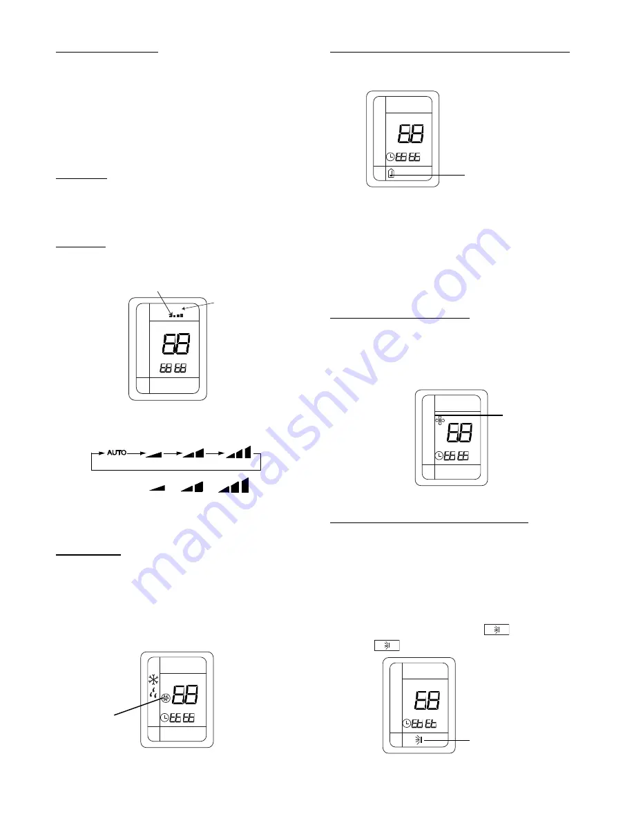
Using Dry Coil Function (X--Fan):
When operating in humid areas, hi--wall units have a DRY COIL
function that will allow the indoor fan to run for a pre--determined
amount of time (10 minutes) after the unit is turned off
(cooling
or dry modes)
to ensure that additional moisture is removed from
coil. Push the “X--FAN” button to enable this feature.
This will
be displayed on remote control.
OPER
º
F
º
C
HOUR
ON/OFF
:
Remote
Dry Coil
Icon
A09637
To deactivate this feature, push the “X--FAN” button again.
Selecting the Horizontal Direction Louver Position
When the unit is turned on, the louvers default to the cooling or
heating position.
If the louver position is not providing adequate comfort due to
room layout or where people are gathered, two options are
available to correct the situation:
Setting the louvers in a stationary position
(other than default for heating and cooling):
The stationary position can be one of five (5) default positions.
To change the louver position, press the
“SWING“ button
once. The
icon is displayed on the remote.
OPER
ºF
ºC
HOUR
ON/OFF
:
Swing Icon
A09640
Summary of Contents for 38GVM Series
Page 14: ...14 WIRING DIAGRAMS A13093 Fig 12 38GVM 18k Wiring Diagram...
Page 15: ...15 WIRING DIAGRAMS CONTINUED A13094 Fig 13 38GVM 24k Wiring Diagram...
Page 16: ...16 WIRING DIAGRAMS CONTINUED A13095 Fig 14 38GVM 30k Wiring Diagram...
Page 17: ...17 WIRING DIAGRAMS CONTINUED A13096 Fig 15 38GVM 36k Wiring Diagram...
Page 18: ...18 WIRING DIAGRAMS CONTINUED A13097 Fig 16 38GVM 42k Wiring Diagram...