background image

18

Step 4 — Complete Electrical Connections

GENERAL — Verify  that  nameplate  electrical  requirements

match available power supply. Voltage at condenser must be

within the minimum and maximum shown in Table 3 and

phases must be balanced within 2%. Contact local power com-

pany for line voltage corrections. Never operate a motor where

a phase imbalance in supply voltage is greater than 2%. Use

the following formula to determine the percentage of voltage

imbalance:

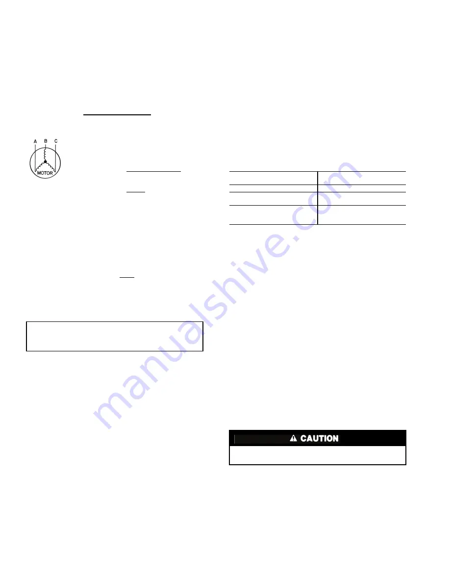
Example: Supply voltage is 240-3-60.

AB = 243 volts

BC = 236 volts

AC = 238 volts

Determine maximum deviation from average voltage:
(AB) 243 – 239 = 4 volts

(BC) 239 – 236 = 3 volts

(AC) 239 – 238 = 1 volt
Maximum deviation is then 4 volts. To determine the percent-

age of voltage imbalance:

This amount of phase imbalance is satisfactory since it is

below the maximum allowable of  2%.

Condenser operation on improper line voltage or excessive

phase imbalance may be considered abuse and any resulting

damage may not be covered by Carrier warranty.

All wiring must be in accordance with NEC (National Elec-

trical Code, U.S.A.) regulations or local codes.
CONNECTIONS — Refer to Table 3 and Fig. 21.

Install a field-supplied disconnect capable of being locked

at OFF position.
POWER 

WIRING 

— 

Install field-supplied branch circuit

fused disconnect(s) of a type that can be locked OFF or OPEN.

Disconnect(s) must be within sight from and readily accessible

from unit in compliance with NEC Article 440-14 (U.S.A.) or

local code.

GENERAL WIRING NOTES

1.

The control


circuit field supply disconnect should

never be open except when unit is being serviced or is

to be down for a prolonged period.

2. Power entry is at one end only.
3. Terminals for field power supply are suitable for cop-

per, copper-clad aluminum, or aluminum conductors.

Insulation must be rated 60 C minimum.

4. Field power supply wires based on minimum 26 C

ambient temperature air are 8 AWG (American Wire

Gage) for Models 09DK034, 044 (208/230-3-60,

230-3-50), 12 AWG for all other models.

5. Connect field power wires to factory-supplied 8 AWG

wire from contactor with factory-supplied nut.

6. Route field wiring through factory-supplied wire ties

and base rail holes. See Fig. 3-5.

7. Control circuit power is as follows:

NOTE: Use 14 AWG (American Wire Gage) copper conductors only
for control circuit wiring.

Step 5 — Add Accessories as Needed —

Accessories include fan cycling head-pressure control, winter

start control, fan cycling, and electrical interlock. Refer to

installation instructions furnished with each accessory.

START-UP

System Evacuation and Dehydration — 

Refer to

GTAC II, Module 4, “Dehydration for Proper Evacuation and

Dehydration techniques.”

Charging Procedure — 

BEFORE CHARGING THE

SYSTEM, INSTALL OR REPLACE THE FILTER-

DRIER(S) CONNECTED TO THE LIQUID LINE WITHIN

THE IN-DOOR UNIT(S) TO PREVENT CONTAMINA-

TION WITHIN THE SYSTEM. Charge to a clear sight glass.

Refer to GTAC II, Module 5 “Charging, Recovery, Recycling,

and Reclamation” and Carrier Refrigerant Service Techniques

manual for proper charging techniques. Add 10 lbs (4.5 kg) of

R-22 over clear sight glass to flood subcooler sections of the

condenser coils. See Table 4 for charging data.

Check Operation of Condenser Fan Motor
Controls and Rotation of Fans — 

R

otation should

be counterclockwise as viewed from top of unit.

% Voltage

Imbalance = 100 x

max voltage deviation

from average voltage

Average voltage

Average Voltage =

243 + 236 + 238

3

=

717

3

= 239 volts

% Voltage Imbalance = 100  x

4

239

= 1.7%

IMPORTANT: If supply voltage phase imbalance is

more than 2%, contact your local electric utility

company immediately.

CONTROL CIRCUIT

V-Hz

POWER

SUPPLY V-Hz

220-60

380-60

230-50

230-50
400-50

115-60

208/230-60

460-60
575-60

Before starting unit, be sure wire fan guards are secured in

place over each fan.

Summary of Contents for 09DK Series

Page 1: ...tions should be per formed by trained service personnel When working on the equipment observe precautions in the literature and on tags stickers and labels attached to the equipment Follow all safety...

Page 2: ...ft 1 22 m for service and for unrestricted airflow on all sides of unit and a minimum of 8 ft 2 44 m clean air space above units See Fig 3 4 and 5 For multiple units allow 8 ft 2 44 m separation betw...

Page 3: ...s are in millimeters Dimensions in are in feet inches UNIT 09DK A B C D E F 020 024 1131 3 81 2 1007 3 311 16 240 97 16 432 1 0 228 0 9 559 1 10 028 1742 5 85 8 1619 5 33 4 496 1 79 16 914 3 0 445 1 5...

Page 4: ...above unit 3 The approximate operating weight of the unit follows 4 Dimensions are in millimeters Dimensions in are in feet inches UNIT 09DK B C D E F 034 112 1 27 16 496 1 79 16 914 3 0 445 1 51 2 76...

Page 5: ...ight of the unit follows 4 Dimensions are in mm Dimensions in are in feet inches 5 Dimension E for 34 9 mm I D is 118 mm 45 8 Dimension E for 28 5 mm I D is 112 mm 47 16 UNIT 09DK A B C D E 044 34 9 I...

Page 6: ...34 size units The following sections describe how to modify the standard unit circuiting as shipped from the factory for optional splits NOTE All coils are purged with dry air and then capped prior to...

Page 7: ...g adjacent joints from heat a Cap the open stub tubes on the left headers where two are located on the gas header and one on the liquid header See Fig 7 Item A b Insert both 35 8 in length tube nipple...

Page 8: ...e protecting adjacent joints from heat a Cap the open stub tubes on the left headers where two are located on the gas header and one on the liquid header See Fig 9 Item A b Insert both 41 16 in length...

Page 9: ...ng adjacent joints from heat a Cap the open stub tubes on the left and right gas and liquid headers with stub tube caps supplied in the parts kit See Fig 11 Item A b Insert the 7 8 in diam header into...

Page 10: ...length as required c Construct one liquid tubing assembly Item C consisting of the following parts and braze it into liquid headers as shown 2 7 8 in OD tubes 1 7 8 in 90 long radius elbow 1 7 8 in t...

Page 11: ...of the following parts and braze it into liquid headers as shown in Fig 13 Item C 2 7 8 in OD tubes cut to length as required 2 7 8 in 90 long radius elbows 1 7 8 in tee see note at right 2 7 8 in OD...

Page 12: ...lowing parts and braze it into liquid headers as shown in Fig 14 Item B 2 5 8 in OD tubes cut to length as required 2 5 8 in 90 long radius elbows 1 5 8 in tee see note at right 3 5 8 in OD nipples cu...

Page 13: ...lowing parts and braze it into liquid headers as shown in Fig 15 Item B 2 5 8 in OD tubes cut to length as required 2 5 8 in 90 long radius elbows 1 5 8 in tee see note at right 3 5 8 in OD nipples cu...

Page 14: ...wn in Fig 16 Item B 2 5 8 in OD tubes cut to length as required 2 5 8 in 90 long radius elbows 2 5 8 in OD nipples cut to length as required c Construct the 47 gas tubing assembly Item C consisting of...

Page 15: ...om heat a Plug the open 11 8 in stub tubes at the inside of each of the large gas headers as shown in Fig 17 Item A Parts required 2 11 8 in plug fittings b Plug the open 5 8 in stub tubes at the insi...

Page 16: ...re relief device one should be field supplied and installed just before the liquid line service valve See Fig 18 and 19 When the split coil is used with multiple systems each system must have its own...

Page 17: ...thdrawn from the receiver Immediately close valves B and C and then open valve A The unit should now be ready for normal operation with the receiver isolated from the system The system should be charg...

Page 18: ...ust be rated 60 C minimum 4 Field power supply wires based on minimum 26 C ambient temperature air are 8 AWG American Wire Gage for Models 09DK034 044 208 230 3 60 230 3 50 12 AWG for all other models...

Page 19: ...30 187 254 20 1 25 6 6 115 200 380 342 418 12 7 20 3 9 220 600 460 414 508 10 1 15 3 3 115 100 575 518 632 11 0 15 3 4 115 UNIT 09DK UNIT FAN MOTORS CONTROL CIRCUIT Volts 3 Ph Supplied Volts MCA MOCP...

Page 20: ...8 9 8 4 9 lb 16 5 22 1 10 9 18 2 21 8 14 5 14 5 7 3 26 9 32 3 21 5 21 5 10 8 R 502 kg 8 3 11 1 5 5 9 2 11 0 7 3 7 3 3 7 13 6 16 3 10 8 10 8 5 4 lb 18 3 24 5 12 1 20 2 24 2 16 1 16 1 8 1 29 9 35 9 23...

Page 21: ...er if the tool is applied across the fins NOTE Use of a water stream such as a garden hose against a surface loaded coil will drive the fibers and dirt into the coil This will make cleaning efforts mo...

Page 22: ...nd fan 3 Loosen nut on motor holding clamp securing motor to motor support 4 Lift motor upward Remove wire connectors Head Pressure Control This feature reduces con densing capacity under low ambient...

Page 23: ......

Page 24: ...manual including Unit Familiarization Maintenance Installation Overview Operating Sequence A large selection of product theory and skills programs are available using popular video based for mats and...

Reviews: