


62-11785
5–20
NOTES
1. If a Data Transfer USB memory device will be used to setup the remainder of the main microprocessor set-
after the settings are entered.
2. After the unit specific and time sensitive configuration settings are complete use the UP or DOWN ARROW
keys until “CONFIGS COMPLETE, = TO EXIT” is displayed in the MessageCenter. Press the ”=” key to
save.
3. If the Configurations, Functional Parameters and DataLink data recorder setup will be set using the display
mounted keys and/or TRU-Tech, continue with following steps.
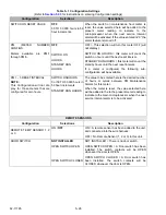
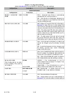
5.5.4
Configurations Using Display Mounted Keys
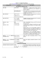
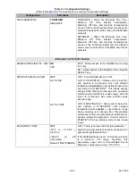
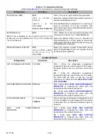
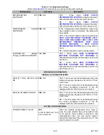
Refer to
for a list of available Configurations. Refer to
for instructions on how to access
them.
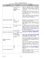
5.5.5
Functional Parameters Via Display Mounted Keys
for a list of available Functional Parameters and
access them.
2. Leave the system powered up as you continue with the next section.
5.5.6
DataLink Data Recorder Via TRU-Tech
NOTE
If the factory settings are used, this section can be skipped.
1. Refer to
for list of DataLink data recorder setups.
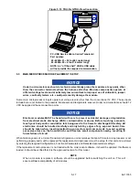
2. Connect a computer to the USB interface port of the unit and start the TRU-Tech program (refer to
).
3. In TRU-Tech, click on the REEFER SETUP LIVE/Data Recorder Tab.
4. Select the Sensors to be recorded and then select averaged or snapshot recordings (averaged is recom-
mended/default for RAT, SAT, AAT and the remote sensors; snapshot is recommended/default for all oth-
ers).
5. When the setup is correct, press the Send button to send the new settings to the system.
6. From the “Confirm Send Information” Pop Up, check the data that is to be sent and un-check the data that is not
to be sent. Click the OK button.
7. Verify that the settings were sent by waiting for the confirmation pop up message.
NOTE
If the DataLink data recorder date and time were not set earlier, they can be set from TRU-Tech.
5.5.7
System Final Checkout
1. Start the unit and allow it to run for a few minutes.
2. While the unit is running, scroll through the Data List. Verify that all the data is now accurately displayed.
3. Initiate a Pretrip test. Allow the unit to complete the Pretrip and check for any alarms. Make any necessary
repairs before returning the unit into service.
Summary of Contents for VECTOR 8100
Page 2: ......
Page 4: ......
Page 12: ...62 11785 viii ...
Page 16: ...62 11640 12 ...
Page 18: ...62 11785 ...
Page 24: ...62 11785 1 6 1 3 SAFETY DECALS ...
Page 25: ...1 7 62 11785 ...
Page 26: ...62 11785 1 8 ...
Page 27: ...1 9 62 11785 ...
Page 28: ...62 11785 1 10 ...
Page 30: ...62 11785 ...
Page 50: ...62 11785 ...
Page 82: ...62 11785 ...
Page 96: ...62 11785 4 14 ...
Page 98: ...62 11785 ...
Page 129: ...5 31 62 11785 ...
Page 130: ...62 11785 5 32 ...
Page 134: ...62 11785 6 4 ...
Page 138: ...62 11785 ...
Page 230: ...62 11785 ...
Page 271: ...8 41 62 11785 ...
Page 272: ...62 11785 8 42 ...
Page 274: ...62 11785 ...
Page 286: ......
Page 287: ......
Page 288: ...62 11785 10 8 ...
Page 292: ......
Page 293: ......