62-10848
3-2
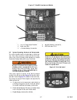
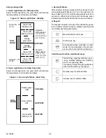
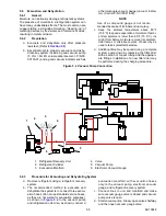
Unit operating LEDs
a. Green Light Status for Standby Units
Under normal operation, the green LED will indicate
the temperature control status as follows:
Figure 3.2 Green Light Status - Standby
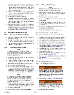
b. Green Light Status for Road Only Units
Under normal operation, the green LED will indicate
the temperature control status as follows:
Figure 3.3 Green Light Status - Road Only
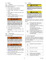
c. Red Light Status
After an alarm has been present for 15 minutes, the red
unit indicating light flashes at 3 Hz. The light will con-
tinue to flash at 0.5 Hz until the temperature returns to
set point ± differential. At that point the steady green
indicator light will light and the alarm become inactive.
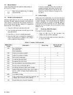
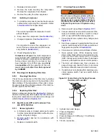
d. Keypad
The keypad consists of six keys that enable the opera-
tor to activate various functions, display operating data
and modify operating parameters.
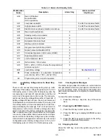
Unit data and function modification keys
SETPOINT
Se 9
q
F
(5
_
C)
Se
differential of
1.8
q
F (1
q
C),
3.6
q
F (2
q
C) or
5.4
q
F (3
_
C)
Setpoint --
differential of
1.8
q
F (1
q
C),
3.6
q
F (2
q
C) or
5.4
q
F (3
_
C)
Setpoint -- 9
q
F
(5
_
C)
Green LED
flashing 3 Hz
Green LED
flashing 0.5 Hz
Steady
green LED
Steady
green LED
Green LED
flashing 0.5 Hz
Green LED
flashing 3 Hz
NULL
BAND
SETPOINT
COOLING
HEATING
Steady green
LED
Green LED is
OFF
Green LED
flashing 1 Hz
NULL
BAND
Manual defrost control key
Unit start-up key
Unit shut-down key in standby or road
mode. On road operation, the unit can
also be shut down with the ignition key.
The SET key, together with the + and -
- keys, enables display and modifica-
tion of unit operating data.
The display scrolls through parameters
each time the SET key is pressed.
Decrease key for selected data
Increase key for selected data

