TB1 – 5 (FWD REF):
The positive 10 VDC reference supply is also short protected and should
normally be loaded by 2k ohms or higher load resistance.
TB1 – 6 & 7 (REF RESET):
Closing a contact across these terminals will instantly reset the
ACCEL/DECEL circuit output to zero and cause the motor to regeneratively brake to a stop at a
rate determined by the C.L. (CURRENT LIMIT) pots. This stopping method (while normally faster
than the quickest controlled deceleration to stop) may subject the motor and A.C. line supply to
higher than normal peak currents. Also, the time to stop in “Current Limit” may not be consistent
due to variables such as motor speed, load level and load inertia.
NOTE:
The Reference Reset contact will have no affect on signals connected to TB1-3, SUMMING
INPUT.
TB1 – 8 & 9 (ENABLE):
Closing a contact across these terminals opens electronic clamps at five
places in the control circuitry and “ENABLES” the drive to function normally. Opening this contact
while running will shut off the control circuit and cause the motor to coast to stop.
TB1 – 10 (+ TACH):
Operation of the control in tachometer feedback requires connection of a 7 or
50 VDC-per-thousand RPM tachometer to terminal 10. When motoring in the Forward direction
(Positive reference voltage), the terminal 10 tachometer voltage should be positive.
NOTE:
Use jumper J2 on the Control Board to select tachometer voltage corresponding to the
motor feedback tachometer rating.
TB1 – 11 (- TACH):
This terminal is also circuit common. The second tachometer lead and
tachometer wiring shield should connect here.
Programing and Adjustments
4.1 Programming Jumpers – Power Board
J1 (A.C. input voltage)
J1 selects the armature feedback voltage level according to the A.C. line voltage to be used. Position at
115V for 115 VAC input or 230 V for 230 VAC input.
J2 and J3 (A.C. input voltage)
The J2 and J3 jumper wires program the power supply transformer according to the A.C. line voltage to
be used. Position each at 115V for 115 VAC input or 230V for 230 VAC input.
4
Carotron RCP200 Series Page 8
Summary of Contents for RCP200 Series
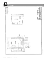
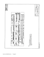
Page 14: ...Prints 6 Carotron RCP200 Series Page 14 ...
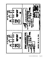
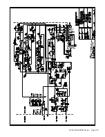
Page 15: ...Carotron RCP200 Series Page 15 ...
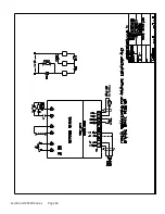
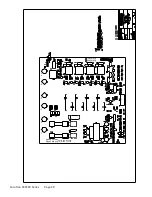
Page 18: ...Carotron RCP200 Series Page 18 ...
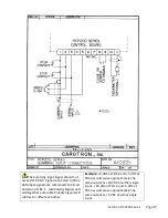
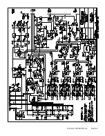
Page 19: ...Carotron RCP200 Series Page 19 ...
Page 21: ...Carotron RCP200 Series Page 21 ...
Page 22: ...Carotron RCP200 Series Page 22 ...
Page 23: ...Carotron RCP200 Series Page 23 ...
Page 24: ...Carotron RCP200 Series Page 24 ...

