


10
5.2 Takeup (Winder) Adjustment Procedure
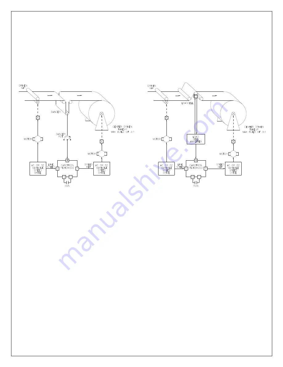
In a takeup application, a Line Speed signal from the lead drive should be connected to
the Summing Input on the PI module. This speed signal will pass through the module
and be present on the output, which is connected to the speed reference of the takeup
drive. The takeup drive’s empty core surface speed should then be scaled to match the
lead drive as close a possible. A feedback device, such as a dancer or loadcell, can
then be used with the PI module to subtract from the Line Speed signal as the diameter
builds and slow the takeup drive down (Figure 4).
Step 1: Select Output Type
1. Select the type of output desired using Jumper J2. If a Voltage output is desired,
select V on J2 and use output terminals 7 (OUTPUT) and 8 (VOLTAGE
RETURN). If a Current output is desired, select I on J2 and use output terminals 7
(OUTPUT) and 9 (CURRENT RETURN).
Step 2: Connections
1. Make connections per drawing C13703 on page 19. Initially, there should be no
connection on the Teach input on terminal 12.
Step 3: Initial Setup
1. Initial commissioning should be performed with the smallest winder core that will
ever be used and without product in the machine.
2. Set Prop Gain potentiometer fully counter clockwise. Set all other potentiometers
to 8 turns clockwise. If the current positions are unknown or in doubt, rotate
potentiometer counter clockwise 20 turns, then clockwise 8 turns.
3. For dancer systems, verify that the full range of motion of the dancer does not
exceed the allowable electrical range (i.e., the potentiometer does not rollover
from min to max or vice versa).
Figure 4: Takeup (Winder) Application Examples
Summary of Contents for PI240-000
Page 1: ...Proportional Integral Loop Module Instruction Manual PI240 000 ...
Page 5: ...5 3 2 Signal Connections Figure 2 General Connections ...
Page 17: ...17 4 Prints 6 6 6 6 ...
Page 18: ...18 ...
Page 19: ...19 ...
Page 20: ...20 ...


