


41
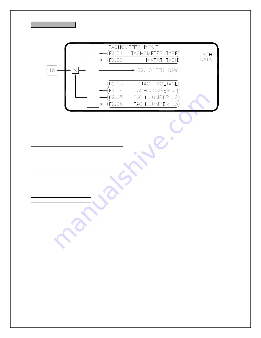
F2: Tachometer Data
This section is utilized only if a motor mounted tachometer is used for speed feedback.
F2.01 Tachometer Type (ICR, Preset: 0 RPM)
Select the type of tachometer used:
AC
or
DC
.
F2.02 Invert Tachometer (ICR, Preset: Off)
The tachometer feedback signal is polarity sensitive. The polarity is used to determine the
direction of rotation of the motor. If the tachometer wires are reversed, this parameter can be
used to invert (i.e. swap) the polarity of the tachometer signal without re-wiring.
F2.03 Tachometer Volts/1000 RPM (ICR, Preset: 50V)
The tachometer feedback signal is polarity sensitive. The polarity is used to determine the
direction of rotation of the motor. If the tachometer wires are reversed, this parameter can be
used to invert (i.e. swap) the polarity of the tachometer signal without re-wiring. Range: 1..250V
F2.04 Tach Jumper J1 (RO)
F2.05 Tach Jumper J2 (RO)
F2.06 Tach Jumper J3 (RO)
The drive calculates the maximum tachometer voltage based on the motor and tachometer data
entered. Jumpers J1-J3 on the control board should be set to these values.
Figure 37
Summary of Contents for EP2020-000
Page 5: ...5 EPx075 000 thru EPx150 000 EPx020 000 thru EPx060 000 PRO 2 2 Physical PRO ...
Page 6: ...6 EPx500 000 thru EPx600 000 PRO EPx200 000 thru EPx400 000 PRO ...
Page 12: ...12 Figure 6 Signal Connections ...
Page 120: ...120 CN8A TB3 CN50 CN1B D14177 REGULATOR BOARD ASSEMBLY ...
Page 121: ...121 CN40 C14188 SNUBBER BOARD ASSEMBLY ...
Page 122: ...122 CN25A C14166 CT ID BOARD ASSEMBLY ...
Page 123: ...123 C14145 PROCESSOR BOARD ASSEMBLY ...
Page 124: ...124 ...
Page 125: ...125 ...
Page 126: ...126 Assembly Drawing 200 400HP Models ...
Page 127: ...127 ...
Page 128: ...128 CN40 ...
Page 129: ...129 CN40 ...
Page 130: ...130 CN40 ...
Page 131: ...131 CN40 ...
Page 132: ...132 Assembly Heatsink Chassis 200 300HP Non Regen Models ...
Page 133: ...133 Assembly Heatsink Chassis 400HP Non Regen Model ...
Page 134: ...134 Assembly Heatsink Chassis 200 300HP Non Regen Models ...
Page 135: ...135 Assembly Heatsink Chassis 400HP Regen Model ...
Page 136: ...136 ...
Page 137: ...137 ...
Page 138: ...138 ...
Page 139: ...139 ...
Page 140: ...140 ...
Page 141: ...141 ...
Page 142: ...142 Wiring Diagram 200 400HP Non Regen Models ...
Page 143: ...143 Wiring Diagram 200 400HP Regen Models ...
Page 144: ...144 ...
Page 145: ...145 ...
Page 146: ...146 ...
Page 147: ...147 ...
Page 148: ...148 ...
Page 149: ...149 ...
Page 150: ...150 PRO V3 FIRMWARE ...
Page 151: ...151 BLOCK DIAGRAM ...
Page 152: ...152 ...
Page 153: ...153 ...
Page 154: ...154 Notes ...