


30
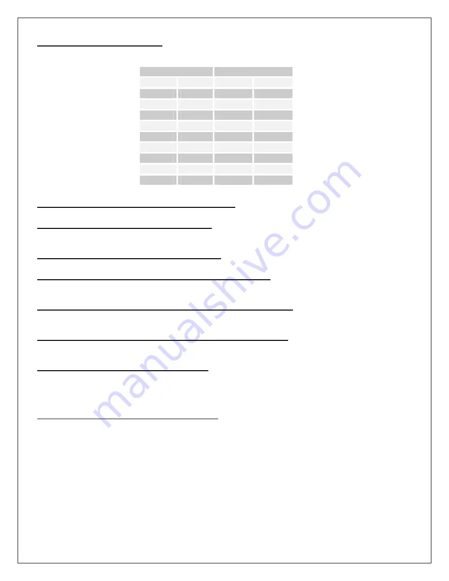
C1.02 Analog Input 1 Status (RO)
Displays the raw analog to digital conversion value. Table 6 below lists the typical status values
for common input levels.
Signal Input
Status
Voltage Current Unipolar
Bipolar
+10V
-
4095
2047
+7.5V
-
3070
1535
+5V
20mA
2047
1023
+2.5V
10mA
1023
511
0V
0mA
0
0
-2.5V
-10mA
-
-512
-5V
-20mA
-
-1024
-7.5V
-
-
-1536
-10V
-
-
-2048
Table 6: Analog Input Status Readings
C1.03 Analog Input 1 Polarity (ICR, Preset: Unipolar)
Configures the type of analog input signal used, either
UNIPOLAR
or
BIPOLAR
.
C1.04 Analog Input 1 Filtering (R/W, Preset: 0)
Sets the level of digital filtering applied to the input signal. The adjustment ranges from 0 (no
filtering) to 15 (heavily filtered). Range: 0..15
C1.05 Analog Input 1 Type (ICR, Preset: Voltage)
Configures the type of analog input signal used, either
VOLTAGE
or
CURRENT
.
C1.06 Analog Input 1 Unipolar 0% Calibration (R/W, Preset: 0)
Defines the minimum signal level in
UNIPOLAR
mode. An input value below this level will be
ignored. Refer to Figure 24. Range: 0..4095
C1.07 Analog Input 1 Unipolar 100% Calibration (R/W, Preset: 4095)
Defines the maximum raw signal level in
UNIPOLAR
mode. An input value above this level will
be ignored. Refer to Figure 24. Range: 0..4095
C1.09 Analog Input 1 Bipolar 100% Calibration (R/W, Preset: 2047)
Defines the maximum raw positive and negative signal levels in
BIPOLAR
mode. Any input
value exceeding this level will be ignored. Refer to Figure 24. Range: 0..2047
C1.10 Analog Input 1 Bias (R/W, Preset: 0.00)
Defines the value of the target parameter when the input signal is less than or equal to the 0%
Calibration. Refer to Figure 24. Note that the formatting of this parameter will change to match
that of the target parameter. For example, if the target parameter is percent, this parameter will
be percent. If the target parameter is Seconds, this parameter will be Seconds.
C1.11 Analog Input 1 Gain (R/W, Preset: 100.00)
Defines the value of the target parameter when the input signal is greater than or equal to the
100% Calibration. Refer to Figure 24. Note that the formatting of this parameter will change to
match that of the target parameter.
Summary of Contents for EP2020-000
Page 5: ...5 EPx075 000 thru EPx150 000 EPx020 000 thru EPx060 000 PRO 2 2 Physical PRO ...
Page 6: ...6 EPx500 000 thru EPx600 000 PRO EPx200 000 thru EPx400 000 PRO ...
Page 12: ...12 Figure 6 Signal Connections ...
Page 120: ...120 CN8A TB3 CN50 CN1B D14177 REGULATOR BOARD ASSEMBLY ...
Page 121: ...121 CN40 C14188 SNUBBER BOARD ASSEMBLY ...
Page 122: ...122 CN25A C14166 CT ID BOARD ASSEMBLY ...
Page 123: ...123 C14145 PROCESSOR BOARD ASSEMBLY ...
Page 124: ...124 ...
Page 125: ...125 ...
Page 126: ...126 Assembly Drawing 200 400HP Models ...
Page 127: ...127 ...
Page 128: ...128 CN40 ...
Page 129: ...129 CN40 ...
Page 130: ...130 CN40 ...
Page 131: ...131 CN40 ...
Page 132: ...132 Assembly Heatsink Chassis 200 300HP Non Regen Models ...
Page 133: ...133 Assembly Heatsink Chassis 400HP Non Regen Model ...
Page 134: ...134 Assembly Heatsink Chassis 200 300HP Non Regen Models ...
Page 135: ...135 Assembly Heatsink Chassis 400HP Regen Model ...
Page 136: ...136 ...
Page 137: ...137 ...
Page 138: ...138 ...
Page 139: ...139 ...
Page 140: ...140 ...
Page 141: ...141 ...
Page 142: ...142 Wiring Diagram 200 400HP Non Regen Models ...
Page 143: ...143 Wiring Diagram 200 400HP Regen Models ...
Page 144: ...144 ...
Page 145: ...145 ...
Page 146: ...146 ...
Page 147: ...147 ...
Page 148: ...148 ...
Page 149: ...149 ...
Page 150: ...150 PRO V3 FIRMWARE ...
Page 151: ...151 BLOCK DIAGRAM ...
Page 152: ...152 ...
Page 153: ...153 ...
Page 154: ...154 Notes ...