Carlton Hurricane RS Owner'S Manual Download Page 45

Hurricane Track          MACHINE OPERATION


25


• 

Continue cutting the stump by adjusting 
the cutting head progressively lower 
until the stump is cut well below ground 
level. 

• 

Raise and swing cutter wheel clear of 
stump and position machine closer to 
stump for next series of passes.  Lower 
and continue cutting. 

• 

Continue in this manner until stump has 
been removed. 

• 

Larger stumps may require repositioning 
machine to work at best advantages. 

• 

IF RED LOW BATTERY LIGHT 
LIGHTS UP ON THE TRANSMITTER, 
THERE IS APPROXIMATELY 20 
HOURS OF BATTERY POWER LEFT. 


• 

Raise cutter wheel clear of stump and 
return to center position.  On the radio 
control transmitter, put the Swing Brake 
switch in the LOCK position before 
moving or turning off the machine. 

• 

Reduce engine speed to idle.  DO NOT 
TURN OFF MOTOR.  Engine must be 
allowed to cool slowly at idle for 3-5 
minutes to avoid damage. 
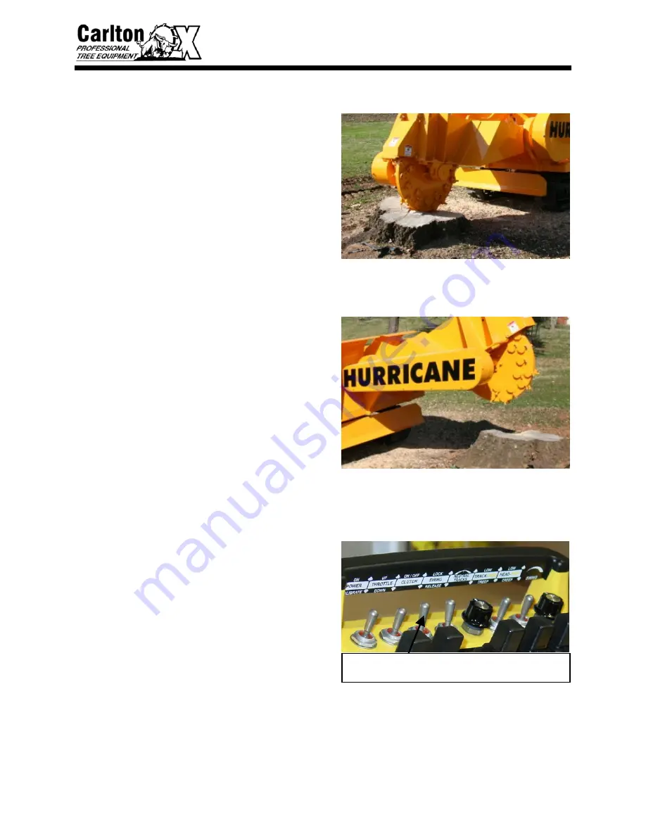
• 

With engine at idle (below 1100 RPM), 
disengage clutch by pushing the switch 
down on the radio control transmitter.  
The clutch will disengage immediately 
and the Clutch Engage light will go off 
on the clutch control panel.  The cutter 
wheel will take several minutes to come 
to a complete stop. 

• 

Move the machine away from the work 
area after the cutter wheel has come to a 
complete stop. 

• 

Turn off machine using key on machine 
control panel.  CLUTCH MUST BE 
DISENGAGED BEFORE TURNING 
MACHINE OFF.  Allow cutter wheel to 
come to a complete stop before 
inspecting the work area. 


DISENGAGE CLUTCH WITH ENGINE AT IDLE.  CLUTCH 

MUST BE DISENGAGED BEFORE TURNING ENGINE OFF

Summary of Contents for Hurricane RS

Page 1: ...__________ Engine Serial _____________ HPTO Clutch Model Spec _____________ Clutch Serial _____________ Purchase Date _____________ Dealer _____________ Carlton J P Carlton Company Div D A F Inc 121 J...

Page 2: ......

Page 3: ...L ENGINE EXHAUST WARNING CALIFORNIA Proposition 65 Warning Diesel engine exhaust and some of its constituents are known to the State of California to cause cancer birth defects and other reproduction...

Page 4: ......

Page 5: ...HURRICANE TRACK SAFETY ALERT...

Page 6: ......

Page 7: ...HURRICANE TRACK SAFETY ALERT...

Page 8: ......

Page 9: ...HURRICANE TRACK SAFETY ALERT...

Page 10: ......

Page 11: ...HURRICANE TRACK SAFETY ALERT...

Page 12: ......

Page 13: ...be liable for consequential damages resulting from breach of warranty IT IS NECESSARY TO RETURN THE WARRANTY VALIDATION FORM AND NOTIFY J P CARLTON CO INC IN WRITING WITHIN TEN 10 DAYS FROM DELIVERY D...

Page 14: ......

Page 15: ...l cost to servicing dealer It is the customers responsibility to deliver machine to dealers facility unless other arrangements have been agreed to between the selling dealer and the customer The manuf...

Page 16: ......

Page 17: ...stop machine and remove key before performing any type of maintenance 4 ______ Customer has been warned not to operate the machine without the cutter wheel guard in place 5 ______ Customer has been fu...

Page 18: ......

Page 19: ...ORT MACHINE 20 MACHINE OPERATION 22 MAINTENANCE MACHINE MAINTENANCE 26 LUBRICATION CHART 29 TROUBLESHOOTING GUIDE 30 SERVICING BELTS 32 SERVICING BEARINGS 42 SERVICING CUTTER WHEEL 44 SERVICING HYDRAU...

Page 20: ......

Page 21: ...iliarizing yourself with the controls and the concepts behind the operation of this machine before attempting to operate it Slowly experiment with the controls and gradually work yourself up to the fu...

Page 22: ...without any prior notification or obligation Inspect your new Carlton Stump Grinder as soon as you receive it Any damages incurred during shipment are not warranted and therefore not covered repairs Y...

Page 23: ...reservoir with lockable cap cover site glass for easy oil level check Large fuel tank with lockable cap cover RS 48 Carbide tipped teeth RS 31 Diameter cutter wheel including teeth TRX 64 Carbide tipp...

Page 24: ...d Ground Wheel Speed 860 RPM Number of Teeth 48 Chip Guards 3 16 Steel Mounted Cutting Dimensions Below Ground 25 Above Ground 53 Cutting Width 18 Diameter Continuous 360 Rotation Hydraulic System Hyd...

Page 25: ...d Ground Wheel Speed 860 RPM Number of Teeth 64 Chip Guards 3 16 Steel Mounted Cutting Dimensions Below Ground 25 Above Ground 72 Cutting Width 19 Diameter Continuous 360 Rotation Hydraulic System Hyd...

Page 26: ...see this symbol The Safety Alert Symbol will be accompanied by one of the following words DANGER WARNING or CAUTION A DANGER symbol means that if the instructions are not followed the possibility of...

Page 27: ...ting hand controls KEEP the swing motor in the locked position when operating hand controls or when servicing the machine BE AWARE that the machine table rotates when the swing rotation is activated A...

Page 28: ...ection and standing at a safe distance Flying debris may cause severe injury Do not operate around water gas power or phone lines Check with property owner or call utilities if not sure Avoid fences a...

Page 29: ...ark machine on level surfaces only Lower cutter head to the ground Do not operate stump cutter in dark dim lit or concealed areas Keep machine clean and clear of debris to eliminate fire hazard It is...

Page 30: ...roken or missing cutter teeth and pockets Inspect bolts hydraulic fittings wiring harnesses hoses and equipment for tightness wear or leakage Make repairs as needed Inspect air filters REPLACE if nece...

Page 31: ...arting the radio control transmitter start the machine On the machine the Speed switch must be in the low position and the Swing Brake switch must be in the locked position before starting the transmi...

Page 32: ...paddle will move both tracks in the same direction forward or reverse The neutral Tracks knob will allow the operator to turn the tracks left or right by twisting the knob in the left or right direct...

Page 33: ...the engine is turned off if a person must be close to the machine for any reason the machine is being transported for travel to from and around the job site or if the machine is to be serviced The bra...

Page 34: ...engine speed must be at idle to engage the cutter wheel CLUTCH The clutch can be engaged from the transmitter To start engagement of the clutch make sure the engine is at idle and push the clutch swi...

Page 35: ...Rev to move machine forward or reverse Use controls opposite Rev Fwd or Fwd Rev of each other to turn machine either right or left When rotating the machine do not leave one track stationary while ro...

Page 36: ...e engine is turned off if a person must be close to the machine for any reason the machine is being transported for travel to from and around the job site or if the machine is to be serviced SCRAPE BL...

Page 37: ...et the cutter wheel started The Power LED light in the upper left illuminates green to show the clutch is receiving switched power from the ignition The Engine Speed Detected LED light illuminates whe...

Page 38: ...ate with the existing unit Or if you have more than one transmitter for this machine it will need to be programmed to communicate with the existing receiver To program the transmitter and receiver you...

Page 39: ...adio control manual Check the light configuration and compare it to the Diagnostic lists in the radio control manual If necessary check the Expansion Module in the same manner If the radio receiver or...

Page 40: ...ING OR UNLOADING THE STUMP GRINDER LOADING RAMPS MUST BE STURDY AND SECURELY ATTACHED TO THE TRAILER BEFORE ATTEMPTING TO LOAD OR UNLOAD THE MACHINE Check trailer for security and make sure chains are...

Page 41: ...utter wheel first When the machine is loaded lower the cutter head and turn off the machine Secure the machine tightly with sufficient tie downs to prevent any movement in transit UNLOADING With trail...

Page 42: ...OPERATE THE SWING FUNCTIONS USING THE MACHINE CONTROL LEVERS ALWAYS KEEP THE SWING BRAKE LOCKED WHEN OPERATING THE MACHINE CONTROL LEVERS FOR POSITIONING DO NOT OPERATE A MACHINE WITHOUT A COMPLETE N...

Page 43: ...ing the Clutch ON OFF switch up on the radio control transmitter and hold for 3 seconds THE PT TECH CLUTCH WILL ONLY ENGAGE WITH THE ENGINE SPEED AT IDLE BELOW 1100 RPM CHECK ENGINE RPM IF CLUTCH WILL...

Page 44: ...e the power to the cutter head swing function The middle position of the switch is HIGH or full power Push the switch up to reduce cutter head speed slightly or push the switch to creep for the slowes...

Page 45: ...switch in the LOCK position before moving or turning off the machine Reduce engine speed to idle DO NOT TURN OFF MOTOR Engine must be allowed to cool slowly at idle for 3 5 minutes to avoid damage Wit...

Page 46: ...NT DO NOT OPERATE A MACHINE WITHOUT A COMPLETE NUMBER OF TEETH IN THE CUTTER WHEEL PROPERLY INSTALLED EXCESSIVE MACHINE VIBRATION WILL OCCUR CAUSING PREMATURE BEARING FAILURE AND EQUIPMENT DAMAGE PLAC...

Page 47: ...when dirty Replace inner safety filter when dirty or when the outer air filter has been changed 3 times Follow engine manual procedure for removal and replacement Do not allow dirt to get into engine...

Page 48: ...valent Inspect all guards bolts nuts and other parts daily for looseness and wear repair as necessary Inspect wiring harnesses for wear and replace if necessary Check cutter wheel pockets and teeth fo...

Page 49: ...NT DO NOT OPERATE A MACHINE WITHOUT A COMPLETE NUMBER OF TEETH IN THE CUTTER WHEEL PROPERLY INSTALLED EXCESSIVE MACHINE VIBRATION WILL OCCUR CAUSING PREMATURE BEARING FAILURE AND EQUIPMENT DAMAGE PLAC...

Page 50: ...hen dirty Replace inner safety filter when dirty or when the outer air filter has been changed 3 times Follow engine manual procedure for removal and replacement Do not allow dirt to get into engine w...

Page 51: ...valent Inspect all guards bolts nuts and other parts daily for looseness and wear repair as necessary Inspect wiring harnesses for wear and replace if necessary Check cutter wheel pockets and teeth fo...

Page 52: ...achines is built to be a rugged performer Your new machine is sturdy and our design goals are simplicity and reliability A regularly scheduled maintenance program will pay big dividends in machine lif...

Page 53: ...far out of pocket Use gauge to set teeth correctly Cutter wheel stops turning Engine belt broke or tension too loose Poly chain belt broke or tension too loose Sheared key in shaft Broken cutter wheel...

Page 54: ...ve control panel cover check and replace fuse Remove control panel cover and check wiring repair if necessary Read PT Tech HPTO manual for further information provided at back of this manual Roar in m...

Page 55: ...R SEVERE INJURY COULD OCCUR POSSIBLY SERIOUS BURNS AND OR DISMEMBERMENT PLACE THE CUTTER WHEEL ON THE GROUND WHEN PERFORMING SERVICE ON A MACHINE DO NOT OPERATE A MACHINE WITHOUT A COMPLETE NUMBER OF...

Page 56: ...ts are used to adjust belt tension by moving the engine Loosen the jam nut on the outside of the plate on each adjustment bolt Then turn the jam nut on the inside of the plate to move the engine back...

Page 57: ...t After replacing the engine belt reposition the engine by loosening the inside jam nuts and then turning the outside jam nuts to pull the engine back into position Turn one adjustment bolt s jam nut...

Page 58: ...ase belt tension Turn one adjustment bolt s jam nut a small amount and then turn the other adjustment bolt s jam nut the same amount working back and forth making adjustments and checking tension unti...

Page 59: ...e Replace belt guard covers and tighten them securely NEVER run a machine without the guards and covers in place and secured properly severe personal injury could occur GENERAL TENSIONING OF V BELT DR...

Page 60: ...EQUIPMENT DAMAGE Special care needs to be taken with your Poly Chain belt Alignment tension and cleanliness of this belt are very important The Poly Chain belt needs to be checked for tension every 7...

Page 61: ...d to loosen the nut closest to the bolt head on each rear jam bolt To loosen the Poly Chain belt move the cutter wheel toward the front of the machine by turning the rear jam bolts on both bearings Wo...

Page 62: ...lt will run at an angle and eventually break if the sprockets are not aligned Adjust the alignment by moving the cutter wheel bushing in or out until the belt is aligned When the belt is aligned tight...

Page 63: ...to adjust belt tension Then the jam bolts and nuts are used to adjust tension When the belt is properly tensioned and the sprockets are aligned tighten the nuts on the bearing bolts There are two nuts...

Page 64: ...nd secured properly severe personal injury could occur POLY CHAIN BELT TENSION Engine HP Engine Belt Poly Chain Belt Deflection Force New Belt Deflection Force Used Belt Deflection 140 HP B173 14m 313...

Page 65: ...ENSURE LONG BEARING LIFE There are two 2 bearings on the cutter wheel shaft These bearings should be purged until new grease is seen before and after every use to keep dirt and moisture out PROPER MA...

Page 66: ...easing the turntable bearing for a full rotation Idle equipment should not be neglected Grease dries out and breathing due to temperature changes can cause condensation within the bearing Whether used...

Page 67: ...ORMING SERVICE ON A MACHINE DO NOT OPERATE A MACHINE WITHOUT A COMPLETE NUMBER OF TEETH IN THE CUTTER WHEEL PROPERLY INSTALLED EXCESSIVE MACHINE VIBRATION WILL OCCUR CAUSING PREMATURE BEARING FAILURE...

Page 68: ...rry like arrangements of teeth to cancel vibration Hurricane TRX tooth pattern shown above Straight teeth are mounted in TWO OPPOSING OUTSIDE POCKETS A straight tooth must have a 45 tooth accompanying...

Page 69: ...ring tooth removal and re installation The locking pin will only lock in the deep slots of the outer teeth Line the slot up with the locking pin slot and insert the pin to lock position The pin will n...

Page 70: ...cturing purposes only It does not refer to the left side of the machine as described in the General Information section Outside pocket teeth are Short Plow Bolt Bits These pockets are angled and welde...

Page 71: ...pin is provided to hold cutter wheel in position during tooth removal and re installation The locking pin will only lock in the deep slots of the outer teeth Line the slot up with the locking pin slo...

Page 72: ...cturing purposes only It does not refer to the left side of the machine as described in the General Information section Outside pocket teeth are Short Plow Bolt Bits These pockets are angled and welde...

Page 73: ...the shank will hit the stump and not the carbide thus causing a lot of vibration Once the shank is angled far enough back then begin sharpening carbide Cut shank with a standard rock and cut the carbi...

Page 74: ...HE GROUND WHEN PERFORMING SERVICE ON A MACHINE WARNING RELEASE HYDRAULIC PRESSURE BEFORE PERFORMING ANY SERVICE TO HYDRAULIC LINES OR OTHER COMPONENTS FLUID UNDER PRESSURE CAN PENETRATE THE SKIN AND C...

Page 75: ...e filter before removing the cover to replace the filter When the cover is removed oil in the container will spill out on the machine Loosen the nut at the top of the filter unit Remove the cover Remo...

Page 76: ...the hydraulic oil level daily and replenish as needed The oil must be checked with the clutch disengaged and the engine off in a cooled condition to get a true oil level reading as heat will cause the...

Page 77: ...Hurricane Track MACHINE WIRING 54...

Page 78: ...9 0250186 Jackshaft Sheave 6B18 4 SF 1 10 Key 3 4 Square x 4 1 11 Key 5 8 x 1 2 x 2 1 12 19040080 Assembly Engine Belt Guard 1 unit 2 pieces 1 13 3 8 16 x 1 HH Bolt 14 14 0150404 3 8 Lock Washer 14 1...

Page 79: ...6 1 9 0250148 Jackshaft Sheave 8B18 4 F 1 10 Key 3 4 Square x 4 1 11 Key 5 8 x 1 2 x 2 1 12 19040074 Assembly Engine Belt Guard 1 unit 3 pieces 1 13 3 8 16 x 1 HH Bolt 26 14 0150404 3 8 Lock Washer 26...

Page 80: ...1 8 Key 3 4 Square x 3 1 2 1 9 Key 3 4 Square x 4 1 4 1 10 0400124B Poly Chain Belt 14MGT 3136 125 1 11 19040077 Weldment Poly Chain Guard 1 12 3 8 16 x 1 HH Bolt 12 13 0150404 3 8 Lock Washer 12 14...

Page 81: ...Square x 3 1 2 1 9 Key 3 4 Square x 4 1 4 1 10 0400124A Poly Chain Belt 14M 3500 125 1 11 19040024 Weldment Poly Chain Guard 1 unit 2 pieces 1 12 3 8 16 x 1 HH Bolt 14 13 0150404 3 8 Lock Washer 14 1...

Page 82: ...TRACK MAINTENANCE 1 RUBBER TRACK ON HURRICANE TRX...

Page 83: ...TRACK MAINTENANCE 2 3 2 1...

Page 84: ...TRACK MAINTENANCE 3...

Page 85: ...TRACK MAINTENANCE 4...

Page 86: ...TRACK MAINTENANCE 5...

Page 87: ...TRACK MAINTENANCE 6...

Page 88: ...TRACK PARTS LIST 7...

Page 89: ...TRACK PARTS LIST 8...

Page 90: ...TRACK PARTS LIST 9...

Page 91: ...TRACK PARTS LIST 10...

Page 92: ...TRACK PARTS LIST 11...

Page 93: ...TRACK PARTS LIST 12...

Page 94: ...TRACK PARTS LIST 13...

Page 95: ...TRACK PARTS LIST 14...

Page 96: ...TRACK PARTS LIST 15...

Page 97: ...TRACK PARTS LIST 16...

Page 98: ...60 Diesel 15 43 70 arc 32 26 5 1 N A 4 300 SP8018 TRX Track Mounted Deutz Turbo 78 Diesel 18 43 80 arc 32 26 5 1 N A 5 420 HURRICANE RS Track Mounted John Deere Turbo 140 Diesel 25 53 360 48 31 1 5 N...

Page 99: ...coil pressure regulating cartridge and a pressure switch are included in the manifold assembly TORQUE SETTING The precise setting of the hydraulic pressure acting on the internal piston controls the t...

Page 100: ...ter plate if required 3 Locate the flywheel mounting bolts found in the plastic bag labeled Flywheel Mounting Bolt They are 3 8 16 UNC by 1 inch long hex head cap screws 4 Install flywheel ring gear t...

Page 101: ...remove the manifold unless rebuilding the HPTO unit See manifold drawing provided for hose fitting sizes and connection locations 13 Install the Microprocessor Controller and all electrical wiring per...

Page 102: ...viced and inspected after 5000 hours of operation If the HPTO unit is allowed to operate beyond this point the torque may drop rapidly and possible damage to the unit could occur SERVICE INSTRUCTIONS...

Page 103: ...ring Item 2 will then be loose Remove Ball bearing 15 Move shaft axially 1 back into position so the retaining ring Item 19 can be removed Important retaining ring must be removed from shaft or damage...

Page 104: ...ining rings Items 33 and verify retaining rings are seated in grooves Shaft Assembly 1 Using bearing heater heat I D of bearing Item 11 to 250 F Using protective gloves slide bearing onto shaft Item 7...

Page 105: ...ity on the outer diameter 5 Using retaining ring pliers install retaining ring Item 19 onto shaft Attention insure that the retaining ring is completely seated in groove in shaft 6 Pack ball bearing I...

Page 106: ...I M BULLETIN HPTO8TD 100 HYDRAULIC POWER TAKE OFF 9 11 2007 8 of 8 Note do not use any washers Note orientation of housing to endcover as shown on assembly drawing...

Page 107: ...ing Item 25 with Mobilfluid 424 or similar oil and install into O D groove in shaft Item 1 9 Lightly coat o ring Item 18 with Mobilfluid 424 or similar oil and install into O D groove in backplate Ite...

Page 108: ...I M BULLETIN HPTO8TD 100 HYDRAULIC POWER TAKE OFF 9 11 2007 10 of 10...

Page 109: ...I M BULLETIN HPTO8TD 100 HYDRAULIC POWER TAKE OFF 9 11 2007 11 of 11...

Page 110: ...02 BH Updated CMCCU 004 drawing with simplified controller cutout F 1 16 03 BH Updated controller functions per firmware B1030106A G 2 3 03 BH cc Added attention note about no washers under the heads...

Page 111: ...pressure regulating cartridge and a pressure switch are included in the manifold assembly TORQUE SETTING The precise setting of the hydraulic pressure acting on the internal piston controls the torqu...

Page 112: ...plate if required 3 Locate the flywheel mounting bolts found in the plastic bag labeled Flywheel Mounting Bolt They are 3 8 16 UNC by 2 inch long hex head cap screws 4 Install flywheel ring gear to e...

Page 113: ...provided at the end of this document 16 Insure that the hydraulic fluid reservoir is filled to the proper fluid level 17 Insure that there is a clean 15 micron minimum oil filter in the hydraulic sys...

Page 114: ...Item 9 from shaft Note Install qty of 3 3 8 16 threaded bolts into holes in piston to assist in piston removal Note backplate Item 14 will come off with the piston 9 Remove all seals from piston shaft...

Page 115: ...n Item 20 o ring Item 40 and die spring Item 23 REBUILD INSTRUCTIONS Refer to exploded view drawing HPTO10TD 100 sheet 2 of 2 Endcover Assembly 1 Apply Loctite 620 to steel cage of seals Items 16 12 2...

Page 116: ...arefully inspect hook piston rings Item 5 Piston rings need to be modified prior to installation SEE CHYPR 008 DRAWING FOR PROPER MODIFICATION PROCEDURES Clean piston rings prior to installation 5 Lub...

Page 117: ...ing Item 13 MOBILITH SHC 220 grease only to 20 capacity on the outer bearing race Note Bearing Item 27 should have a shoulder on one side and no grease from factory Using bearing press fixture install...

Page 118: ...re are no metal burrs or chips inside threaded center hole of shaft after removing threaded rod 5 Install hex o ring plug Item 30 into shaft end and tighten until snug 6 Install die springs Item 41 qt...

Page 119: ...ner wrench install clamp nut Item 35 onto end of shaft Tighten locknut until backplate Item 14 stops moving 18 Torque lockscrew on clamp nut Item 35 to 70 lb in 19 Install o ring Item 40 into accumula...

Page 120: ...I M BULLETIN HPTO8TD 100 HYDRAULIC POWER TAKE OFF Page 10 of 10...

Page 121: ...I M BULLETIN HPTO8TD 100 HYDRAULIC POWER TAKE OFF Page 11 of 11...

Page 122: ...hematic to callout hose for HPTO12 unit C 12 29 03 BH Removed controller documentation and created a separate controller I M Bulletin D 1 26 04 BH Added warning against plugging and pressurizing manif...

Page 123: ...5 FAULT RPM TOO HIGH while attempting to engage 5 FAULT RPM TOO HIGH while attempting to disengage 5 FAULT TIMED LOCKOUT 5 FAULT OIL PRESSSURE Loss 6 FAULT SAFETY SWITCH 7 FAULT COIL FAULT 7 Remote St...

Page 124: ...the system If coil voltage does not match the voltage source contact PT Tech prior to installation ATTENTION IN THE EVENT OF AN EQUIPMENT EMERGENCY E STOP POWER MUST STILL BE SUPPLIED TO THE CONTROLLE...

Page 125: ...r through the opening in the machine s control panel 8 Connect the Deutsch 12 pin connector from the wiring harness to the back of the microprocessor controller WARNING to avoid any electrical malfunc...

Page 126: ...etermines how the HPTO unit will function during startup The following information describes the controller functions Power LED Indicator The Power LED illuminates to notify the operator that the cont...

Page 127: ...ionally increased while the clutch was still bumping This is considered an aborted startup attempt If the operator keeps the speed above 1100 rpm and re attempts clutch engagement then the RPM TOO HIG...

Page 128: ...d stalls the engine due to a locked rotor the controller will go into immediate lockout regardless of how many failed start attempts have occurred FAULT OIL PRESSSURE Loss The Oil Pressure Switch is a...

Page 129: ...h is engaged if this switch opens the clutch will not disengage This feature only prevents the clutch from engaging FAULT COIL FAULT Attached to the hydraulic manifold is a DC coil that controls the e...

Page 130: ...utton on the front of the controller This remote switch must be a momentary switch only The controller will draw the following amps when the remote button is pushed 5volts the draw will be 10mA 12volt...

Page 131: ...ing section of this manual 4 Allow the engine to run at idle speed for a sustained period of time to allow the hydraulic oil to reach a normal running temperature prior to engaging the HPTO Clutch 5 T...

Page 132: ...no break in the wire Check that the wire connected to pin 7 on the back of the controller is not losing momentary power while the engine is cranking Engine Speed Detected LED fault While the engine is...

Page 133: ...SURE Check the following items Check all hoses for leaks Check reservoir fluid level Check oil filter Check cooler for a leak Check pressure switch wires for a cut wire Install a pressure gauge with a...

Page 134: ...easure the resistance between the two coil wires at the coil The two wires at the controller may need to be cut in order to take this measurement The Ohm readings should be as follows 12 volt coil 6 4...

Page 135: ...I M BULLETIN CMCCU 004 BASIC CONTROLLER Page 13 of 13...

Page 136: ...I M BULLETIN CMCCU 004 BASIC CONTROLLER Page 14 of 14...

Page 137: ...ring harness schematic per ECN 144 B 3 12 04 BH Added coil ohm measurement to coil fault troubleshooting section C 4 26 04 BH Updated wiring harness schematic D 4 27 04 BH Updated controller images to...

Page 138: ......

Page 139: ......

Page 140: ......

Page 141: ......

Page 142: ......

Page 143: ......

Page 144: ......

Page 145: ......

Page 146: ......

Page 147: ......

Page 148: ......

Page 149: ......

Page 150: ......

Page 151: ......

Page 152: ......

Page 153: ......

Reviews: