background image

EN

IT IS THE RESPONSIBILITY OF THE EMPLOYER TO PROVIDE THIS INFORMATION TO THE OPERATOR OF THE EQUIPMENT.

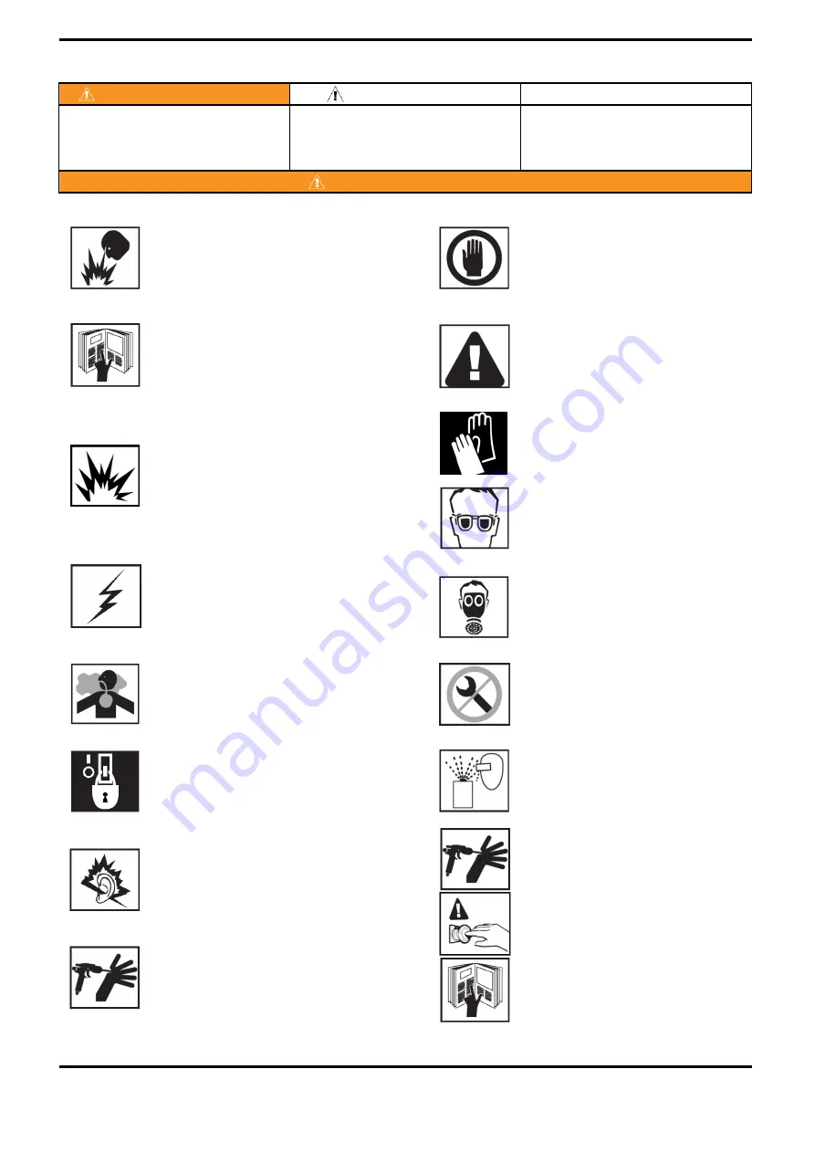
NOISE LEVELS. The A-weighted sound level of pumping and spray equipment 
may exceed 85 dB(A) depending on equipment settings. Actual noise levels 
are available on request.  It is recommended that ear protection is worn at all 
times while equipment is in use.

PRESSURE RELIEF PROCEDURE. Always follow the pressure 
relief procedure in the equipment instruction manual.

OPERATOR TRAINING. All personnel must be trained before 
operating finishing equipment.

HIGH PRESSURE CONSIDERATION. High pressure can cause serious 
injury.  Relieve all pressure before servicing. Spray from the gun, hose leaks or 
ruptured components can inject fluid into your body and cause extremely 
serious injury.

WARNING

PROJECTILE HAZARD. You may be injured by venting liquids or 
gases that are released under pressure, or flying debris.

Important installation, operation or maintenance 

information.

INSPECT THE EQUIPMENT DAILY. Inspect the equipment for 
worn or broken parts on a daily basis. Do not operate the 
equipment if you are uncertain about its condition.

FIRE AND EXPLOSION HAZARD. Never use 1,1,1-Trichloroethane, 
Methylene Chloride, other Halogenated Hydrocarbon solvents or fluids 
containing such solvents in equipment with aluminium wetted parts. Such use 
could result in a serious chemical reaction, with the posibility of explosion. 
Consult your fluid suppliers to ensure that the fluids being used are compatible 
with aluminium parts.

STATIC CHARGE. Fluid may develop a static charge that must be dissipated 
through proper grounding of the equipment, objects to be sprayed and all other 
electrically conductive objects in the dispensing area.  Improper grounding or 
sparks can cause a hazardous condition and result in fire, explosion or elecrtic 
shock and other serious injury.

TOXIC VAPOURS. When sprayed, certain materials may be poisonous, create 
irritation, or are otherwise harmful to health. Always read all labels, safety 
sheets and follow any recommendations for the material before spraying. If in 
doubt contact your material supplier.

Hazards or unsafe practices which could result in 

severe personal injury, death or substantial 

property damage.

LOCK OUT / TAG-OUT. Failure to de-energise, disconnect, lock out and tag-
out all power sources before performing equipment maintenance could cause 
serious injury or death.

Read the following warnings before using this equipment.

SOLVENTS AND COATING MATERIALS. Can be highly flammable or 
combustible when sprayed. Always refer to the coating material supplier's 
instructions and safety sheets before using this equipment.

WEAR SAFETY GLASSES. Failure to wear safety glasses with 
side shields could result in serious eye injury or blindness.

READ THE MANUAL. Before operating finishing equipment, read and 
understand all safety, operation and maintenance information provided in the 
operation manual. Users must comply with all local and national codes of 
practice and insurance company requirements governing ventilation, fire 
precautions, operation and house-keeping of working areas.

CAUTION

WARNING

WEAR RESPIRATOR. The use of respiratory protective 
equipment is recommended at all times. The type of equipment 
must be compatible with the material being sprayed.

NEVER MODIFY THE EQUIPMENT. Do not modify the 
equipment unless the manufacturer provides written approval.

In this part sheet, the words WARNING, CAUTION and NOTE are used to emphasise important safety information as 
follows: 

NOTE

GLOVES. Must be worn when spraying or cleaning the 
equipment.

Hazards or unsafe practices which could result in 

minor personal injury, product or property 

damage.

EQUIPMENT MISUSE HAZARD. Equipment misuse can cause 
the equipment to rupture, malfunction or start unexpectedly and 
result in serious injury.

KNOW WHERE AND HOW TO SHUT OFF THE EQUIPMENT 
IN CASE OF AN EMERGENCY.

SB-E-2-990 R6.0

4/24

www.carlisleft.com

Summary of Contents for DeVILBISS AGMDPRO-102-HV30C-K

Page 1: ...OT DESTROY II 2 G X T6 AGMDPRO Automatic Spray Gun It is the Customer s responsibility to have all operators and service personnel read and understand this manual Contact your local Carlisle Fluid Technologies representative for additional copies of this manual SB E 2 990 R6 0 www carlisleft com ...

Page 2: ... violent and lead to an equipment explosion 3 5 6 bar 51 87 psi 15 bar 217 psi 12 bar 174 psi P3 Cylinder Air Pressure P2 Max Fluid Input Recirculation Pressure P1 Max Air Input Pressure FUNCTIONAL DESCRIPTION SPECIFICATIONS FLUID AND AIR INLET PRESSURES ENVIRONMENTAL MATERIALS OF CONSTRUCTION Gun Head and Fluid Passageways P1 Air Inlet Size 120 x 46 x 46 Electroless Nickel Plated Brass Gun Body M...

Page 3: ...constructional safety c Notified body details and role II 2 G X T6 This Product is designed for use with Protection Level Providing all conditions of safe use installation stated within the product manuals have been complied with and also installed in accordance with any applicable local codes of practice Signed for and on behalf of Carlisle Fluid Technologies UK Ltd D Smith Director of Sales EMEA...

Page 4: ...C VAPOURS When sprayed certain materials may be poisonous create irritation or are otherwise harmful to health Always read all labels safety sheets and follow any recommendations for the material before spraying If in doubt contact your material supplier Hazards or unsafe practices which could result in severe personal injury death or substantial property damage LOCK OUT TAG OUT Failure to de ener...

Page 5: ...Feed FLUID NEEDLE TABLE 1 See table 2 See table 1 AGMDPRO Round Spray HVLP High Efficiency FLUID NOZZLE AIR CAP Head Recirculation TABLE 2 Stainless Steel Size construction PART No R40 Plastic Tipped FLUID NOZZLE 0 5 PRO 205 05 K AGMDPRO 301 05 07 K TE40SC PRO 205 07 K AGMDPRO 301P 05 07 K 0 7 AGMDPRO FLUID NOZZLE AND NEEDLE RANGE HIGH EFFICIENCY HVLP TE30C TE50C AGMDPRO 102 TE30C K AGMDPRO 102 R4...

Page 6: ...iciency High Efficiency High Efficiency High Efficiency 300mm 380mm 380mm 300mm 250 400 ml min 250 400 ml min 250 400 ml min 200 300 ml min 2 Bar 30 psi 2 Bar 30 psi 2 Bar 30 psi 2 Bar 30 psi Recommended Air Inlet Pressure Typical Fluid Flow Typical Fan Pattern Size 315mm 160 200 ml min 1 75 Bar 26 psi 450 L min 16 0 cfm AGMDPRO 102 HV30C K HVLP Air Cap Type Part Number Air Consumption Flow rates ...

Page 7: ...EN EXPLODED VIEW SB E 2 990 R6 0 7 24 www carlisleft com ...

Page 8: ... 1 K SN 98 K2 AGMDPRO 1 1 K INDEXING HEAD ASSY 4 CAM 1 PISTON ASSEMBLY 1 AGMDPRO 8 K5 AGMDPRO 1 1 U K INDEXING SPRAY HEAD 1 SPRAY HEAD GASKET 1 1 QTY PARTS LIST DESCRIPTION PART No 10 AGMDPRO 408 K 1 1 AIR CAP RETAINING RING SEE TABLE 1 1 RETAINING RING SEALS 1 RETAINING RING 1 RETAINING RING SEAL 1 AIR CAP 2 3 1 O RING AGMDPRO 29X K5 AGMDPRO 9 K2 PACKING KIT OF 5 1 BODY END PLATE 1 AGMDPRO 12 K E...

Page 9: ...ctrostatic charges which may be created by fluid or air flows This can be achieved through the spray gun mounting or conductive air fluid hoses Electrical bond from the spray gun to earth should be checked and a resistance of less than 10 Ohms is required SB E 2 990 R6 0 9 24 www carlisleft com ...

Page 10: ...otection Flush the equipment fluid passageways with appropriate solvent before use NOTE Mat R Mat 1 8 G 1 8 G 1 8 x 6mm 1 8 x 8mm 1 8 x 8mm Connection Size Fluid Recirculation Fluid Cylinder Air Fan Air Atom Air Supply 3 5 1 2 1 2 2 3 3 4 4 5 5 1 2 SB E 2 990 R6 0 10 24 www carlisleft com ...

Page 11: ...EN 5mm Make sure indexing legs and slots are engaged before tightening the Air Cap ring OPERATION Gun Removal and Gun Mount Indexing Air Cap 90 SB E 2 990 R6 0 11 24 www carlisleft com ...

Page 12: ...orque of 18 1 20 35 Nm 13 4 15 lbf ft Packing Removal Component direction arrow for dis assembly and sequence number Note Reverse for assembly Nozzle and Needle Removal Warning Check all air and fluid pressure is removed before starting maintenance MAINTENANCE 3 SB E 2 990 R6 0 12 24 www carlisleft com ...

Page 13: ...EN 3mm 1 8 2 2 Nm 1 3 1 6 lbf ft 3mm 3mm 5mm MAINTENANCE Cam Removal Piston and Spring Removal SB E 2 990 R6 0 13 24 www carlisleft com ...

Page 14: ...terior or partially plugged fluid tip Replace fluid tip or air cap if necessary CORRECTION CONDITION CAUSE TROUBLESHOOTING SPRAY PERFORMANCE Determine if the obstruction is on the air cap or the fluid tip Do this by making a test spray pattern Then rotate the cap one half turn and spray another pattern If the defect is inverted obstruction is on the air cap Clean the air cap as previously instruct...

Page 15: ...input air pressure Increase air pressure Atomising air pressure too low Heavy centre pattern Pattern adjustment valve set too low Turn out counter clockwise to achieve correct pattern Too much material Reduce fluid flow by turning fluid needle adjusting screw clockwise Reduce fluid pressure Intermittent or fluttering spray fan Loose fluid tip Tighten Fluid tip not seated correctly in gun head Remo...

Page 16: ... for smaller size or change air cap for different specification air cap Excessive bounce back Too much atomisation air pressure Reduce air pressure Gun too far from surface Check distance normally 150 200mm Material too thin Mix properly or apply light coats reduce fluid flow Gun tilted at an angle Mount gun at right angle to work Gun too far from surface Check distance Too much air pressure Reduc...

Page 17: ... spits paint when triggering on and off Incorrect needle fitted to gun Check fluid tip needle selection chart and fit correct item Open fluid needle adjustment knob Check air supply and air line Fluid needle adjustment knob not open enough CORRECTION Will not spray Paint build up on fluid tip Paint build up on air cap Damaged air cap holes Replace with new air cap Gradual build up of bounce back o...

Page 18: ...lean and reassemble with new or clean air cap FLUID FAULTS CAUSE CORRECTION Slow fluid leak from fluid tip and needle seat Fluid tip internal seat scored damaged or worn Replace Contamination on needle or tip mating surfaces preventing good seal Thoroughly clean Incorrect fluid tip for fluid needle fitted to gun Check tip needle selection chart and fit correct item Sluggish needle Lubricate packin...

Page 19: ...edle packing Fluid needle packing worn or loose Tighten or replace as necessary AIR FAULTS CAUSE CORRECTION CORRECTION Major fluid leak or fluid jetting from fluid tip and needle seat Contamination on needle or tip mating surfaces preventing good seal Remove tip and needle and thoroughly clean Incorrect fluid tip for fluid needle fitted to gun Check tip needle selection chart and fit correct item ...

Page 20: ...d onto intermediate plate ASSEMBLY FAULTS CAUSE CORRECTION Spray gun does not locate onto intermediate plate Locking cam is not in the unlock position Turn locking cam to the unlock position using a 5mm key Turn locking cam to the unlock position using a 5mm key Spray gun cannot be removed from intermediate plate Locking cam is not in the unlock position SB E 2 990 R6 0 20 24 www carlisleft com ...

Page 21: ... AGMDPRO 29X K5 AGMD 142 LOCKING PIN AIR TUBE KIT OF 2 O RING KIT OF 5 SCREW 1 2 5 Included in Cam Kit AGMDPRO 406 K Removable location pin can be removed so intermediate plate can be fitted to existing Special machine adaptors without modification Note Further machine adaptors and robot mounted adaptors available on request 3 AGMDPRO 403 K MACHINE ADAPTOR REF PART No DESCRIPTION QTY 1 SB E 2 990 ...

Page 22: ...EN NOTES SB E 2 990 R6 0 22 24 www carlisleft com ...

Page 23: ...EN NOTES SB E 2 990 R6 0 23 24 www carlisleft com ...

Page 24: ...x 1 800 445 6643 Europe Africa Middle East India Tel 44 0 1202 571 111 Fax 44 0 1202 573 488 Carlisle Fluid Technologies is a global leader in innovative finishing technologies Carlisle Fluid Technologies reserves the right to modify equipment specifications without prior notice 2019 Carlisle Fluid Technologies Inc DeVilbiss Ransburg MS BGK and Binks are registered trademarks of Carlisle Fluid Tec...

Reviews: