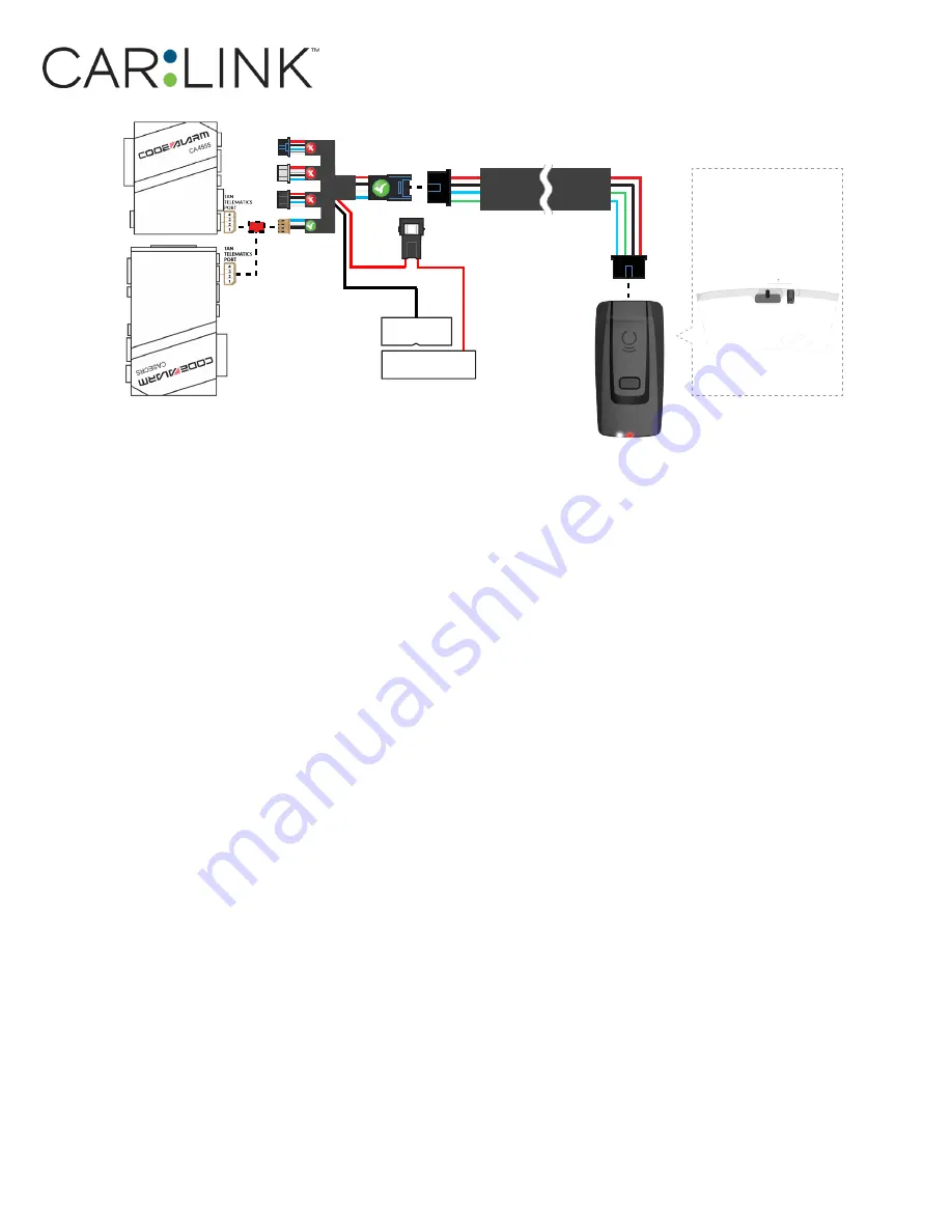
CarLink CLBTLR Installation & Programming Manual Download Page 37

Antenna:

 Cord length 9 feet

Installation: 

Place antenna 3 inches 
(minimum) from any obstructions

Orientation: 

Vertical; antenna 

facing downwards (as seen in 
diagram)

HRN-CRF

-02

(+) 

12V BATTERY 

(1)

GROUND 

(1)

3

(1) Connect when using with  CODE ALARM.

OR

STEP 2. CONNECT

STEP 3. ADD A DEVICE/VEHICLE TO AN ACCOUNT

a.  Download the App and Log into your account (see page 2 of this document for details)
b.  Click the “+” sign at the bottom right of the Application screen.  This will allow you to temporarily add 

and configure your customers system inside your personal account.  A system refers to the Antenna    

being installed in the windsheild of the vehicle. 

c.  Before adding a system to your device, ensure the remote starter IS NOT armed/locked or in Valet mode 

and set the ignition of the vehicle to the On position.

d.  Then Tap to “Scan QR Code” and use the smartphone camera to scan the QR Code located on top of the 

antenna.  

e.  Once connected, the system is in “Installer Mode”.  Follow the on-screen instructions for configuring the 

system.

STEP 4. PRE-CONFIGURE THE APPLICATION EXPERIENCE FOR YOUR CUSTOMER

a.  Start by setting the protocol of the antenna being used.  This is acheived by selecting the Brand, Model 

and protocol used inside the Remote starter.  When done, click on “Confirm”.  System will now try to 

communicate with the remote starter to confirm that all settings related to protocol are valid.

b.  Once back in the control panel, click on the Settings Gear at the top right of the screen and edit the 

Vehicle name, configure the Auxiliaries that might have been added (if applicable) and click “OK” when 

done.  Then choose the vehicle to display inside the control panel in the VEHICLE IMAGE section and 

click OK.  

c.  When your configurations are all completed, click “OK” at the top right corner.  All Configurations will 

take effect.

STEP 5. TESTING THE SYSTEM

When the system is connected and fully configured, testing can begin.  Test all the application functions 

(Start, Stop, Lock, Unlock, Auxiliaries, Etc.)  When testing is completed, tap on the “installer icon” at the top 

of control screen.  When prompted Click “Yes, and delete system from account” since this is the installer 

mode and not the End User mode. This will make the system “Ready for Customer Delivery”.  
Also make sure that the Owners Card is handed to the Owner of the vehicle or attached to the vehicle    

keychain.  Doing this will ensure that the instructions on how to setup their App, Account and add the Sys-

tem is done correctly by using the system QR Code affixed on the windsheild mounted antenna. 
 

NOTE : UNDER ANY CIRCUMSTANCES, PLEASE DO NOT REMOVE THE QR CODE FROM THE ANTENNA!

INSTALLATION, WIRING & PROGRAMMING GUIDE

Summary of Contents for CLBTLR

Page 1: ...er will accept no responsability for any electrical damage resulting from improper installation of this product be that either damage to the vehicle itself or to the installed device This device must...

Page 2: ...44 DSE iSTART2 3 46 System LED Status Protocol Reference Chart 48 Reset Procedure 48 CREATE AN ACCOUNT Before begining the installation and setting the configurations of a Carlink CLBTLR system we st...

Page 3: ...HARDWARE PARTS XTX 3000 IVU CAB 4W HRN CRF 02 RTX 3200...

Page 4: ...te starter please follow this procedure in order to configure correctly your remote starter a Go to www idatalink com and click on Flash your module b Using the new Weblink configurator Choose vehicle...

Page 5: ...em will now try to communicate with the remote starter to confirm that all settings related to protocol are valid b Once back in the control panel click on the Settings Gear at the top right of the sc...

Page 6: ...te starter please follow this procedure in order to configure correctly your remote starter a Go to www idatalink com and click on Flash your module b Using the new Weblink configurator Choose vehicle...

Page 7: ...e Settings Gear at the top right of the screen and edit the Vehicle name configure the Auxiliaries that might have been added if applicable and click OK when done Then choose the vehicle to display in...

Page 8: ...ote starter to accept the RF kit system When flashing the iDatastart BM or BZ remote starter please follow this proce dure in order to configure correctly your remote starter a Go to www idatalink com...

Page 9: ...em will now try to communicate with the remote starter to confirm that all settings related to protocol are valid b Once back in the control panel click on the Settings Gear at the top right of the sc...

Page 10: ...starter to accept the RF kit system When flashing the AKX or OEM remote starter please follow this procedure in order to configure correctly your remote starter a Go to www idatalink com and click on...

Page 11: ...em will now try to communicate with the remote starter to confirm that all settings related to protocol are valid b Once back in the control panel click on the Settings Gear at the top right of the sc...

Page 12: ...starter to accept the RF kit system When flashing the AKX or OEM remote starter please follow this procedure in order to configure correctly your remote starter a Go to www idatalink com and click on...

Page 13: ...rter When done click on Confirm System will now try to communicate with the remote starter to confirm that all settings related to protocol are valid b Once back in the control panel click on the Sett...

Page 14: ...the RF kit system When flashing the Compustar or Polarstart remote starter please follow this procedure in order to configure correctly your remote starter a Go to www idatalink com and click on Flas...

Page 15: ...e Settings Gear at the top right of the screen and edit the Vehicle name configure the Auxiliaries that might have been added if applicable and click OK when done Then choose the vehicle to display in...

Page 16: ...kit system When flashing the CM 7200 remote starter please follow this procedure in order to configure correctly your remote starter a Go to www idatalink com and click on Flash your module b Under th...

Page 17: ...e Settings Gear at the top right of the screen and edit the Vehicle name configure the Auxiliaries that might have been added if applicable and click OK when done Then choose the vehicle to display in...

Page 18: ...flashing the Compustar DC2 remote starter please follow this procedure in order to configure correctly your remote starter a Go to www idatalink com and click on Flash your module b Using the new Webl...

Page 19: ...e Settings Gear at the top right of the screen and edit the Vehicle name configure the Auxiliaries that might have been added if applicable and click OK when done Then choose the vehicle to display in...

Page 20: ...flashing the Compustar DC3 remote starter please follow this procedure in order to configure correctly your remote starter a Go to www idatalink com and click on Flash your module b Using the new Webl...

Page 21: ...e Settings Gear at the top right of the screen and edit the Vehicle name configure the Auxiliaries that might have been added if applicable and click OK when done Then choose the vehicle to display in...

Page 22: ...F kit sys tem When flashing the DBALL 2 remote starter please follow this procedure in order to configure cor rectly your remote starter a Go to www directechs com and click on Flash module b Choose v...

Page 23: ...ings Gear at the top right of the screen and edit the Vehicle name configure the Auxiliaries that might have been added if applicable and click OK when done Then choose the vehicle to display inside t...

Page 24: ...kit system When flashing the DB3 remote starter please follow this procedure in order to configure correctly your remote starter a Go to www directechs com and click on Flash module b Choose vehicle M...

Page 25: ...ings Gear at the top right of the screen and edit the Vehicle name configure the Auxiliaries that might have been added if applicable and click OK when done Then choose the vehicle to display inside t...

Page 26: ...r to accept the RF kit system When flashing the 4X10 5X10 AF D600 ASD200 ASD600 remote starter please follow this procedure in order to configure correctly your remote starter a Go to www directechs c...

Page 27: ...ings Gear at the top right of the screen and edit the Vehicle name configure the Auxiliaries that might have been added if applicable and click OK when done Then choose the vehicle to display inside t...

Page 28: ...e RF kit system When flashing the DS4 DS4 remote starter please follow this procedure in order to configure correctly your remote starter a Go to www directechs com and click on Flash module b Choose...

Page 29: ...ings Gear at the top right of the screen and edit the Vehicle name configure the Auxiliaries that might have been added if applicable and click OK when done Then choose the vehicle to display inside t...

Page 30: ...ng the Prestige E Model remote starter please follow this procedure in order to configure correctly your remote starter a Open Internet Explorer 11 and go to WWW VEPROG COM b Click on Detect Device bu...

Page 31: ...he screen and edit the Vehicle name configure the Auxiliaries that might have been added if applicable and click OK when done Then choose the vehicle to display inside the control panel in the VEHICLE...

Page 32: ...flashing the Prestige Z model remote starter please follow this procedure in order to configure correctly your remote starter a Go to www idatalink com and click on Flash your module b Then click on F...

Page 33: ...e Settings Gear at the top right of the screen and edit the Vehicle name configure the Auxiliaries that might have been added if applicable and click OK when done Then choose the vehicle to display in...

Page 34: ...updating the Prestige E Model remote starter please follow this procedure in order to configure correctly your remote starter a Open Internet Explorer 11 and go to WWW VEPROG COM b Click on Detect Dev...

Page 35: ...rter When done click on Confirm System will now try to communicate with the remote starter to confirm that all settings related to protocol are valid b Once back in the control panel click on the Sett...

Page 36: ...accept the RF kit system When updating the Code Alarm CASECRS CARS or CA4555 remote starter please follow this procedure in order to configure correctly your remote starter a Open the Code Alarm Utili...

Page 37: ...tarter When done click on Confirm System will now try to communicate with the remote starter to confirm that all settings related to protocol are valid b Once back in the control panel click on the Se...

Page 38: ...YSTEMS XTX 3000 IVU CAB 4W OLDER CODE ALARM HRN CRF 02 STEP 1 CONFIGURE THE REMOTE STARTER The Older Code Alarm remote starter are already pre configured to accept the RF kit system No extra programmi...

Page 39: ...tarter When done click on Confirm System will now try to communicate with the remote starter to confirm that all settings related to protocol are valid b Once back in the control panel click on the Se...

Page 40: ...he RF kit system Please make sure to use a BLADE AL 64 and update the firmware to the latest firmware available Follow this procedure in order to configure correctly your remote starter a Go to www id...

Page 41: ...ings Gear at the top right of the screen and edit the Vehicle name configure the Auxiliaries that might have been added if applicable and click OK when done Then choose the vehicle to display inside t...

Page 42: ...pt the RF kit system Please make sure to use a BLADE AL 64 and update the firmware to the latest firmware available Follow this procedure in order to configure correctly your remote starter a Go to ww...

Page 43: ...ings Gear at the top right of the screen and edit the Vehicle name configure the Auxiliaries that might have been added if applicable and click OK when done Then choose the vehicle to display inside t...

Page 44: ...TION OF DSE 503AIR 5R 85 XTX 3000 IVU CAB 4W DSE 503AIR 5R85 STEP 1 CONFIGURE THE REMOTE STARTER The 503Air is already pre configured to accept the RF kit system No extra programming required INSTALLA...

Page 45: ...n Confirm System will now try to communicate with the remote starter to confirm that all settings related to protocol are valid b Once back in the control panel click on the Settings Gear at the top r...

Page 46: ...kit system When flashing the iStart2 iStart3 remote starter please follow this procedure in order to configure correctly your remote starter a Go to www idatalink com and click on Flash your module b...

Page 47: ...n Confirm System will now try to communicate with the remote starter to confirm that all settings related to protocol are valid b Once back in the control panel click on the Settings Gear at the top r...

Page 48: ...ics protocol ADS TEL ADS TEL or DRONE 4x Flashes Fortin protocol Fortin 2 Fortin 2 5x Flashes Compustar protocol COM COM 6x Flashes Posse protocol Voxx Tel Voxx Tel 7x Flashes N A N A N A 8x Flashes N...

Page 49: ...INSTALLATION WIRING PROGRAMMING GUIDE...

Page 50: ...2018 Lightwave Technology Inc All rights reserved 400 Wright St Laurent Quebec H4N1M6 CANADA...

Reviews: