


Model EZGas Pro gas burner — Instruction manual
MNEZGas 011917
– 20 –
Where appliance instructions differ from this manual, follow the appliance instructions.
7. Troubleshooting
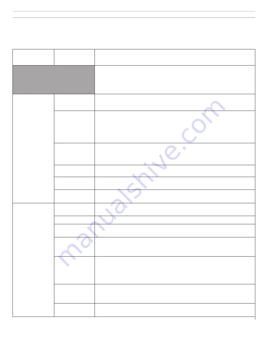
Problem
Possible
Cause
Corrective Action
WARNING
These procedures must only be performed by a qualified service technician. Use care
when performing tests on electrically or mechanically live parts. Disconnect power to
burner/appliance and close main manual gas valve when removing components for
service. Failure to comply could result in severe personal injury, death or substantial
property damage.
Burner motor will
not start
120 VAC power
circuits
Check voltage and polarity at entrance to appliance and burner. Check fuse or breaker
protecting circuit. Check appliance limit circuit – are controls calling for heat? Check
electrical connections.
Primary control is
in Lockout
When a Lockout occurs, the screen turns on, the fault icon flashes and a fault mes-
sage is displayed. The screen will cycle every 4 seconds between 2 displays, one
giving the fault message and one giving the amount of time in the lockout state. For
example, if the cause was loss of the CO input the fault icon would flash and the
message would read “CO detected.” After 4 seconds, the time in the lockout state
“secs or mins” will be displayed. This cycle will continue until the fault is resolved
.
Primary control is
in Latch-up
When Latch-up occurs, the fault icon will flash and the screen will show “Latch-up”
along with time spent in Latch-Up state. See page 15 for the procedure to handle this
condition. When resetting the 60200FR control from Latch-up, be sure to investigate
what caused the repeated failures. Correct the condition.
Incorrect wiring
Check wiring against appliance and burner wiring diagrams. Verify all connections
are secure.
Defective motor
Remove motor leads from junction box and apply power directly. If motor fails to
operate, then replace.
Defective primary
control
If control receives power to both the black and red/white wires and TT input is closed
but doesn’t start the motor, the control may be defective. Replace control.
Repeated flame
failures – burner
won’t light
Airflow too high
Check air band setting against Table 1, page 7. Reposition to correct setting if neces-
sary.
Gas orifice wrong
Check gas orifice size. See pages 7 and 8 for procedure.
Wrong manifold
pressure
Check combination gas valve outlet pressure – should be between 3.2 and 3.8 inches
w.c. unless specified.
No gas supply to
combination gas
valve
Check main manual gas valve – might be closed. Attach manometer to combination
gas valve supply pressure tapping and check pressure. If no pressure, trace gas line
to find why no gas is available.
Gas valve not
opening
Check gas supply pressure to combination gas valve. Pressure in excess of 14
inches w.c. will cause valve to lock up.
Check voltage to gas valve. Is gas valve receiving 24 VAC? If gas valve is receiving
24 VAC and not opening and gas supply pressure is belopw 14 inches w.c., replace
gas valve.
Airflow switch
Check electrical connections and sensing connections to airflow switch. If blower
operates, check across switch to see if it closes.
If switch is correctly connected but won’t close, replace airflow switch.
Primary control
defective
Check voltage to gas valve during TFI. If no voltage to valve, replace control.


