background image

3

Before you begin assembling your 

Yak 54 ARF

, take some

time to read through this entire instruction book.  It is

designed to take you step-by-step through the process and

to give you added information on engine and radio selection

and set-up, balancing your aircraft, and flying your model.

The time you spend will speed the assembly process and

help you avoid problems.

PREPARING FOR ASSEMBLY

You will need a work area of approximately 24 x 70" which has been

covered to protect it from adhesive, as well as cuts and other

damage. Many people cover their work area with a sheet of

dry wall (sheet rock) and/or waxed paper t o prevent CA

Glue and Epoxy from ruining the work surface.

CONSTRUCTION TIPS

IMPORTANT: ALWAYS READ A FEW STEPS AHEAD.

This will alert you to coming instructions and will help you

plan accordingly.

Using the Parts Identification section, familiarize yourself

with the various items included in your kit box.
As you work, CHECK OFF EACH STEP in the box provid-

ed, so that you are sure you do not forget anything.
Do not hesitate to ask questions.  Your local hobby dealer

and area flyers will most likely be happy to help, as they

want you to have a successful flying experience.  You may

also receive technical assistance from Carl Goldberg

Products, Ltd.  by telephone 1-678-450-0085.

ADHESIVES & GLUING TECHNIQUES

CA adhesives are specially formulated to firmly glue the ply-

wood, hardwood, and balsa used in your model and to with-

stand the vibration and stresses of high performance flight.

However, there are times, such as when you are installing

the stabilizer and fin on the fuselage and want more set-

up time for careful alignment and positioning, then you

should use epoxy.. Occasionally, you also will want to use

thin CA, which "wicks" into the surrounding areas. Aliphatic

resin glue or similar water-based glues can also be used,

but they will add to the assembly time because they dry so

much more slowly than CA glue.  Remember,  when ever

using any CA, you must be careful to read instructions thor-

oughly, as you will have only seconds for positioning of

parts.  Be sure to trial fit parts together before gluing.  Also,

never use watery THIN type CA glue for gluing plywood and

hardwood parts.  Thin CA's do not adequately bond these

areas.

CAUTION

Some people may experience an allergic reaction when

exposed to fumes from CA glue or epoxy.  As with paints,

thinners, and solvents, it is always important to use glues

only where there is adequate ventilation to carry fumes

away.  A fan is recommended.  Also, special care must be

taken when using CA, as it will bond skin as well as other

surfaces.   Before using any CA, carefully read all label pre-

cautions. When using CA, protective eye-wear and care in

keeping the glue away from the face is highly recommend-

ed.  If CA does happen to get into the eye, hold lid open and

flush with water only.  Seek immediate medical attention.

COVERING

The Yak 54 ARF is covered in  a premium polyester film

chosen by many of the world's top flyers for its beauty,

toughness, and ease of application and repair.  It is not

uncommon for ARF's to develop a few wrinkles in transit.  If

this is true of your model, the situation is easily corrected.

Before you begin putting the pieces together, run over the

surface of each section with an iron (either specially

designed for airplane use or the more cumbersome house-

hold iron) or use a modeling heat gun.   Apply the heat (set

at about 350° F), following along with a soft cloth and press-

ing down on the covering as you go around.  This will more

firmly set the covering adhesive into the wood and keep

your aircraft covering tight and smooth in the future.
One of the great advantages of polyester film is that it can

be applied over itself without causing gas bubbles.  This

allows you to repair your aircraft, as well as to customize it

in a number of ways.  If, due to a flight mishap, you get a

hole or similar covering damage, simply trim away the

ragged edges and then apply a patch, following the direc-

tions that come with your covering , which is available at

your hobby dealer. 

Important Information

Covering coming loose is not COV-
ERED UNDER WARRANTY. Due to
temperature changes the plane may
develop some wrinkles in the cover-
ing that you will need to remove with
an iron. Be sure to seal the edges
down first so that you do not cause
the covering to shrink and leave
exposed areas of wood. Please
inspect the plane before beginning
to assemble to make sure you are
happy with it. After assembly has
begun you cannot return the kit. If
you find a problem before beginning
to assemble the plane you must
contact us, please do not return it to
the dealer.

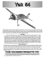
Summary of Contents for Yak 54

Page 1: ...d to immediately request a replacement of any parts he believes to be defective for their intended use The company warrants replacement of any such components provided the buyer requests such replacement with in a period of 90 days from the date of purchase and provided the defective part is returned if so requested by the company No other warranty expressed or implied is made by the company with ...

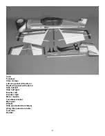
Page 2: ...ft wing panel with aileron Right wing panel with aileron Stab half left Stab half right Elevator left Elevator right Motor mounts Tail wheel bracket Main gear Wheels Stab spars aluminum tubes Wing tube aluminum tube Fuel tank Rudder ...

Page 3: ...t adequately bond these areas CAUTION Some people may experience an allergic reaction when exposed to fumes from CA glue or epoxy As with paints thinners and solvents it is always important to use glues only where there is adequate ventilation to carry fumes away A fan is recommended Also special care must be taken when using CA as it will bond skin as well as other surfaces Before using any CA ca...

Page 4: ...ue 885 Flame red 883 and White 870 TOOLS AND SUPPLIES FOR ASSEMBLY MODELING OR UTILITY KNIFE WORK SURFACE 24 X70 ELECTRIC DRILL 1 16 3 32 1 8 3 16 5 32 1 4 5 64 7 32 DRILL BITS SMALL STANDARD PHILLIPS SCREW DRIVERS MASKING TAPE NEEDLE NOSE PLIERS MOTO TOOL 24 RULER FLEXIBLE STRAIGHT EDGE 30 60 90 x 6 TRIANGLE SOFT PENCIL A FEW STRAIGHT OR T PINS ADJUSTABLE WRENCH WIRE CUTTER DYKES OPTIONAL HEAT GU...

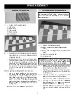
Page 5: ...owing pictures may not exactly match the hardware you are using Always check the radio manufacturer s instructions when installing radio equipment 1 Collect the following items 4 Servo mounting screw supplied with radio 1 Servo with rubber grommet supplied with radio 2 Servo extensions 12 2 y connectors IMPORTANT To ensure that any connections locat ed inside the wing will not come loose either wh...

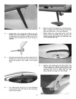
Page 6: ...HINT Drill the hole from the bottom half way Then drill down to the hole from the top of the aileron 5 Insert the 6 32 x 3 screw from the top through the aileron Place the nylon washer and the nylon ball nut on the bolt and tighten Screw the adjustable clevis assemble on the bolt 6 Thread on to one end of a 4 40 x 4 pushrod a nut and clevis Mount the pushrod onto the nylon clevis assemble on the a...

Page 7: ...tab half onto the tubes and tightly against the fuselage side Install the two 4 40 x 1 2 bolts into the mounting tabs on the bot tom of fuselage Blind nuts are pre mounted in the fuselage Be sure to use lock tite on the bolts Repeat for the other stab half 3 Install the control horns on the elevators in the same manner as you did the ailerons 4 Because of the location of the stab tube the inboard ...

Page 8: ...ole at the location you just marked Drill half way from each side as you did on the ailerons 1 Collect the following items 2 Landing gear legs 6 6 32X3 4 Socket head screws 6 6 flat washers 2 Wheel pants one left one right 2 4mm axels with lock nuts 4 4mm wheel collars 2 3 1 4 wheels 2 4 40 x t nuts 2 4 40 x 1 2 socket head bolts 2 Slide gear leg into slot on side of fuselage and install retaining...

Page 9: ... in each pant The 1 8 hole for the mounting bolt must be drilled 7 Remove the wheel pant and drill a 5 32 hole at the location you marked Insert the blind nut on the inside and pull it tight using the 4 40 mounting bolt Lock in place with CA glue being careful not to get it in the threads 6 Block the tail of the plane up so that the fuse lage is sitting level Put the wheel inside the pant and slid...

Page 10: ... 2 Build up the tail wheel assembly by putting the tail wheel on the axel and retaining with the 1 8 wheel collar Install the bracket collar without holes on each side on the shaft Insert the shaft through the mounting bracket and install the bracket collar Screw the thread ed rods into the bracket on each side Make sure the tiller arms are square to the tail wheel and tighten the screw Use lockti...

Page 11: ...ll pull rudder servo setup The rud der servo can be mounted in the tail if a heavy motor is used and weight is need in the rear The 1 2 to 1 6 two and four stroke motors are not heavy enough to mount the servos in the tail 4 Thread the 2 3 4 pushrod into the clevis assembly on the rudder horn Install the nut and metal clevis on the other end and attach to servo arm Install the clevis keeper Repeat...

Page 12: ... on the cockpit floor and back against the bulkhead 5 If you are using a large motor you may want to install a piece of tri stock not included along the front side of the servo tray and the bottom of the wing tube This will add strength to the servo tray Rudder Servo 1 Collect the following parts 2 braided steel cable 2 metal clevis 2 4 40 nuts 2 clevis retainers 4 threaded cable couplers 4 cable ...

Page 13: ...coupler with cable attached into the nylon clevis assembly on the rudder horn 5 Thread the cable into the access hole in the side of the fuselage Repeat for the other cable rudder cable access hole threaded coupler with cable 6 Take the other two threaded couplers and install a nut and clevis on each 7 Install the two clevis assemblies on a double control arm Center the servo and attach the contro...

Page 14: ...ewall Note The firewall will have a 1 hole in the center not shown on the photo 3 Clamp your motor between the beams of the two mounts and set flat on the work bench Make sure the motor is square to the table and both mounts sit flat Put a scrap piece of wood in the prop mount and measure both sides to make sure it is square The distance from the table to the front of the thrust washer scrap wood ...

Page 15: ... throttle output arm on your engine and insert the nylon tube for the throttle pushrod Throttle Servo 1 Collect the following items 1 e z servo connector 1 Laser cut plywood mount 1 2 56 threaded one end pushrod 1 2 56 clevis 1 clevis retainer 5 With the motor on the mounts center the mounts on the two line you drew on the fire wall Mark the location of the holes and drill a 160 diameter hole at e...

Page 16: ...r and install on your servo arm 6 Thread the 2 56 clevis on the pushrod and insert into the plastic tube Connect the clevis to the throttle arm on the motor Connect the other end of the pushrod to the e z connector on the throttle servo and adjust 2 Assemble the throttle servo mount by gluing the 3 8 square rails in the corners of the 1 8 plate and gluing the triangle gussets under the rails ...

Page 17: ...rt one on the left side The tubes should extend out the front of the cap 5 8 Bend the long tube up at about a 20 degree angle This should be adjusted so the end of the tube almost touches the top of the tank when installed 4 Install the 4mm silicone tube to the short brass tube and install the clunk to the other end of the silicone tube This is the fuel pickup and must be free to flop around in th...

Page 18: ...pieces of paper making sure the stripes line up and cowl is straight Use masking tape to hold the cowl in place Transfer the holes from the paper to the cowl Drill a 7 32 hole at the four locations The blind nuts are pre installed in the mounting blocks Fit the 1 4 long pieces of silicone tub ing in the holes and insert the 4 40 x1 2 screws with a flat washer on top The silicone tubing will act as...

Page 19: ...r Mark the location of the paper on the fuselage so you can relocate it after the cowl is reinstall 5 Reinstall the cowl and fit the paper in place on the fuselage and mark the location of the hole for the muffler Repeat for the other holes in the cowl 6 When mounting the cowl for flight use locktite on all the bolts ...

Page 20: ...g 1 Collect the following items 1 Hatch 1 Canopy 2 4 40 screws 2 Fit the hatch in place with the dowels in front and the tabs in the rear 3 Use the two 4 40 screws through the side of the fuselage to hold in place mounting screw ...

Page 21: ...r you to fly the Yak at As you get comfortable you can move the CG back further The fur ther you move the CG the more wild the aerobatics will become BUT the more unstable the Yak will become Throws We have provided two sets of throws Use the lower throws on the first flights then work your way up to the higher throws Do not use the higher throws till you are ready LOW HIGH Elevator 1 UP Down All ...

Reviews: