background image

15

Wild Stick .40

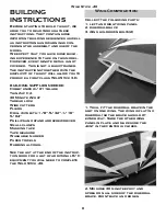
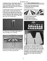
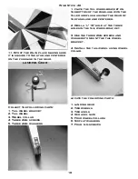
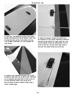
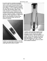
5. Locate one of the 2mm pushrods,
metal clevis, silicone clevis keeper,
and nylon swing in keeper. Make sure
the clevis is screwed on the pushrod
with about 1/16” of threads showing
on the inside of the clevis. Install the
clevis on the control horn. make
sure the servo is centered and the
aileron is in neutral. Mark the loca-
tion of the wire where it crosses the
control horn and bend at a 90 degree
angle. Cut the angle off at 3/8”.
Install the pushrod in the control
horn and retain using the nylon
swing in keeper.

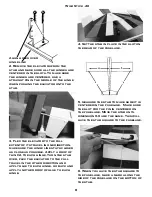
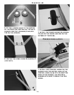
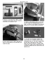
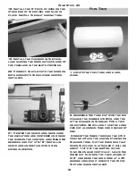
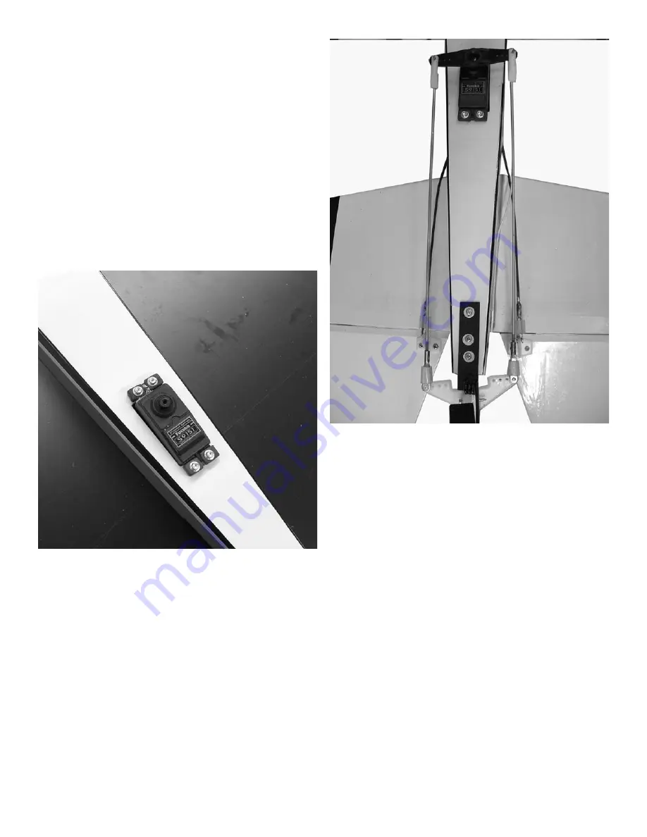
6. Install the rudder servo in the bot-
tom of the fuselage at the rear using
hardware supplied with radio.

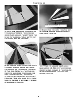
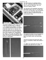
7. Install the rudder pushrods the
same way we installed the aileron
pushrod. Locate two 2mm x 30cm
pushrods, install the clevises on the
horns, center the rudder and servo.
Mark the bend at the servo end and
bend 90 degrees. Cut off at 3/8”.
Install in servo arm and retain with
nylon swing in keeper.

Summary of Contents for Wild Stick .40

Page 1: ... G GO OL LD DB BE ER RG G P PR RO OD DU UC CT TS S L LT TD D P O Box 818 Oakwood GA 30566 678 450 0085 Fax 770 532 2163 www carlgoldbergproducts com copyright 2004 Carl Goldberg Products Wild Stick 40 Wild Stick 40 ...

Page 2: ...pressed or implied is made with respect to the merchandise sold by the company The buyer acknowledges and under stands that he is purchasing only a component kit from which the buyer will himself construct a finished flying model airplane The company is neither the manufacturer of such a flying model airplane nor a seller of it The buyer hereby assumes the risk and all liability for personal or pr...

Page 3: ...rcraft in an intelligent manner THROTTLE MANAGEMENT IS A MUST We at Lanier have put the Wild Stick 40 through a very rigorous flight testing schedule and have stressed the airframe beyond all practical parameters without a single fail ure Lanier will NOT warrant the Wild Stick 40against flutter due to improp er set up or excessive speed maneuvers having said that we believe you will find the Wild ...

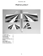
Page 4: ...4 Wild Stick 40 Parts Layout 1 Fuselage 1 2 Wing Halves 2 3 Ailerons 4 4 Stabilizer 1 5 Elevator Halves 2 6 Fin 1 7 Rudder 1 8 Landing Gear 1 9 Dihedral Brace 1 ...

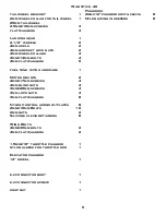
Page 5: ...ith hardware 1 Motor mounts 2 4mmx17mm screws 4 4mm blind nuts 4 3mmx20mm screws 4 3mm lock nuts 4 3mm flat washers 8 Nylon Control horns w plates 8 2mmx16mm Bolts 16 2mm nuts 2 Silicone clevis retainers 8 Wing Bolts 4mmx30mm bolts 2 4mm flat washers 2 1 5mmx16 throttle pushrod 1 nylon sleeve for throttle rod 1 Elevator pushrod 14 dowel 1 e z connector body 1 e z connector screw 1 snap nut 1 Pushr...

Page 6: ...hin Zap CA 30 Minute Z poxy Thread lock Wire cutters Pliers Drill with bits 1 8 5 32 1 16 5 64 Phillips and standard screwdriver Small clamps Masking tape Tape measure Washable marker Paper towels Rubbing alcohol See the list at the end of the instruc tion book for a list of additional R C equipment you will need to complete the Wild Stick 40 Wing Construction Collect the following parts 1 left an...

Page 7: ...a poor joint 5 locate the two 4mm x 45mm bolts and two 4mm flat washers 6 After the epoxy has cured bolt the wing in place on the fuselage Tail construction locate the following parts 1 stabilizer with elevators 2 Fin with rudder 3 Nylon control horns 4 nylon nut plates 5 2mm x 20mm screws 6 Silicone clevis keepers 1 locate the control horns on the inside edge of the elevators on the bottom side m...

Page 8: ...ly a drop of thin CA to each hinge Turn the stab over flex the elevator to the full travel in the other direction and apply glue to each hinge go back and apply another drop of glue to each hinge 4 Set the stab in place in the slot on the rear of the fuselage 5 measure the stab to make sure it is centered in the fuselage Make sure the slot for the fin in centered on the fuselage Move the stab unti...

Page 9: ...use Reinstall the stab and check to make sure it is square use pins to hold in place Check the alignment with the wing by sighting from the front and rear Apply pres sure to one side if necessary to make stab parallel to wing remove covering 9 Remove the covering from the bot tom portion of the rudder where it plugs into the stab remove covering 10 Fit the fin in place and make a mark around it Re...

Page 10: ...1 place the tail wheel bracket on the bottom of the fuselage with the tiller are flush against the rear of the fuselage and centered 2 Drill a 1 16 hole at the three holes in the tail wheel bracket 3 Use the three 2mm screws and washers to mount the tail wheel bracket 4 Install the tail wheel using wheel collar locate the following parts 1 landing gear 2 Two wheels 3 Two axels 4 two axel nuts 5 Fo...

Page 11: ...ws 6 install the axels using the aircraft lock nuts 7 install the wheels using one wheel collar on the inside and one on the outside of the wheel Rudder installation 1 install two control horns on the rudder with the bottom edge of the control horn flush with the bottom edge of the rudder use two 2mm screws with nuts to mount the two horns ...

Page 12: ... of the fin and does hit it as it swings from side to side Apply a drop of thin CA to each hinge Deflect the rudder in the opposite direction and apply another drop of glue to each hinge on the opposite side Engine Installation locate the following parts 1 Two motor mounts 2 Four 4mmx25mm screws 3 Four 4mm blind nuts 4 Four 4mmx35mm bolts 5 Four 4mm aircraft lock nuts 6 8 4mm flat washers 1 Clamp ...

Page 13: ...iece of wire to pull the nuts into place 5 pull the nuts up with the wire then install the bolt and washer through the hole and tighten to finish pulling the blind nut into the hole 6 After all four nut are pulled tight install the engine using the four 4mm bolts and washers Use lock tite on the bolts Radio Installation 1 For the Ailerons you will need four servos and two 12 servo exten sions ...

Page 14: ...rons using the same method used on the elevators Center all hinges and use thin CA to glue in place making sure you have full deflection in both directions and a tight hinge line 4 Use a straight edge to mark the location of the four aileron horns in line with the output arm install the four horns using the 2mm bolts and nylon plates Align over the hinge line as we did on the elevators ...

Page 15: ...t crosses the control horn and bend at a 90 degree angle Cut the angle off at 3 8 Install the pushrod in the control horn and retain using the nylon swing in keeper 6 Install the rudder servo in the bot tom of the fuselage at the rear using hardware supplied with radio 7 Install the rudder pushrods the same way we installed the aileron pushrod Locate two 2mm x 30cm pushrods install the clevises on...

Page 16: ... 10 Bend a 90 degree angle in the end of the throttle pushrod and cut at 3 8 Attach to the throttle arm and retain with a nylon swing in keeper 11 locate the pushrod connector and attach it to a servo arm It has a washer on top of the arm the bottom of the arm then install nut Use a drop of CA glue on nut to make sure it does not come loose Make sure the pushrod connector will rotate in the servo ...

Page 17: ...or if necessary nylon tube 13 Locate the 14 wooden dowel two 12 threaded rods with clevis one 6 piece of 2mm wire and two pieces of Shrink tubing 14 Take the two pushrods and bend a 90 degree angle at 8 1 2 on one and 8 11 16 on the other The difference in length will make the ends even after you install them in the holes in the wooden dowel 15 insert the ends of the pushrods in the pre drilled ho...

Page 18: ... 8 Install in servo arm and retain with nylon swing in keeper Fuel Tank 1 Locate the fuel tank and hard ware 2 Assemble the tank cap with the big washer the rubber stopper and the little washer in the rear For a two line system we will only use the long piece of aluminum tube and one short one 3 Insert the tubes through the stop per and attach the silicone tubing on the short one Cut the tubing so...

Page 19: ... can get The four aileron setup gives you sev eral options If you want to fly the plane in a normal setup just use three y connectors and connect all four aileron servos into the aileron channel This will give a normal aileron setup Because of the large size the roll rate will be really rapid If you want just flaps and ailerons you can use two y connec tors and plug the two outside servos into the...

Page 20: ...the different flight modes be sure to have plenty of altitude for your first tries Because of the large con trol surfaces the plane can get out of control very quickly if you are not ready for it or if you have something not set up correctly If the flight modes are not set up correctly the plane could be unflyable in that con figuration so be ready to turn it off if you cannot handle it Thank you ...

Reviews: