23
30% Ultimate ARF
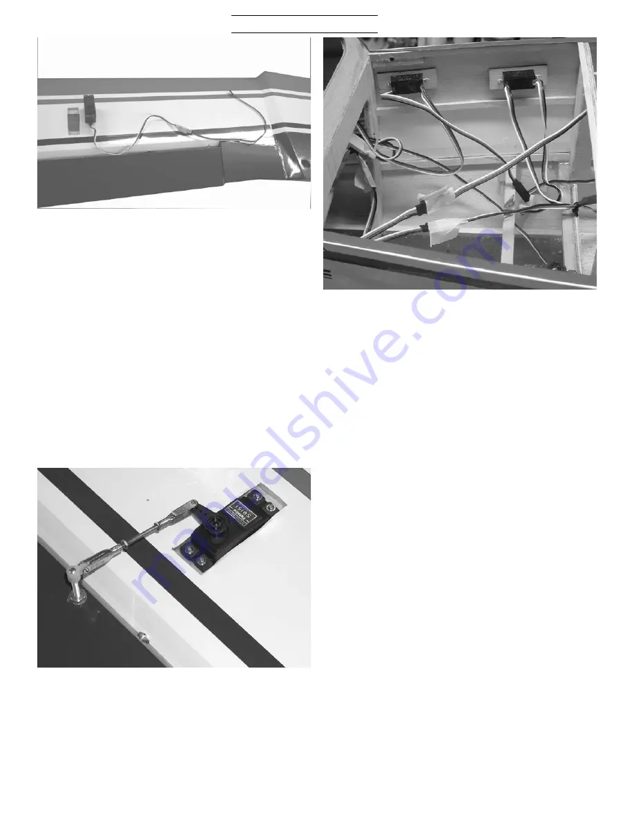
Locate the four aileron servo
cutouts in the bottom side of both
wings. Remove the covering with a
sharp knife. You will need four 14”
servo lead extensions. There is a
string located in each cutout to pull
the wire through to the center sec-
tion. Locate the two 3/4” holes in the
top side of the bottom wing in the cen-
ter and the bottom of the top wing in
the center. Remove the covering over
these holes. Attach the string you
your servo lead and pull through
wing. Mount the servo with the hard-
ware supplied with the radio with the
output arm to the rear.
Locate the two 4-40 x 2-1/8”
pushrods, clevises, nuts, and retain-
ers. Attach the pushrod between
servo arm and aileron control horn.
After controls are adjusted tighten
the nuts against the clevis and
install retainers.
Locate the two switches, one radio
one motor, just below the hatch rail
just in front of the turtledeck bulk-
head on one side. You can glue a cou-
ple of rails (not supplied) across the
fuselage in this area to mount the
receiver and two batteries on. The
CG will probably require this area to
be used. You will need an 18” servo
lead extension to reach the throttle
servo, a y-connector to plug in the
two rudder servos, two y-connectors
to plug in the ailerons, plus two 12”
extensions. If you have a computer
radio you can plug the elevator ser-
vos into different channels, if not
you will need a servo reverser.
There is a hole in the balsa just
inside the right rear cabane strut.
You can remove the covering and
pass the y-connector through. Cable
tie the y-connector to the cabane
struts so the two ends are at the top
where the leads come out of the top
wing.


