Cargo Floor B.V.
P.O. Box 271
7740 AG COEVORDEN
The Netherlands
Phone: +31 (0)524-59 39 00 www.cargofloor.nl
Fax: +31 (0)524-59 39 99
CF500 cylinder repair regulations, Article No. 9305003
03-09-2008 / GB 24 of 26
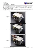
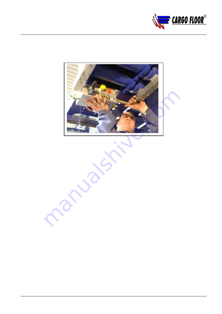
Suspend the valve (with the short pipe installed) between the common rails on the bottom and on the
rod side; figure 47. Turn the coupling screw on the screw-in coupling of the common rail on the rod
side. Next, install the block on the common rail on the bottom using the 4 bolts (M8 x 75).
Install both the other pipes (P5 and S5) and, when everything has been installed, secure them.
Tighten the 4 bolts (M8 x 75) of the common rail with a torque wrench (30 Nm).
Next, first install the G02 cartridge with coil and afterwards the GS02 cartridge with coil.
Connect the plug caps again.
Remark:
NOTE! The plug cap with the red LED should be position on the coil of the GS02 cartridge and
the plug cap with the yellow LED should be positioned on the coil of the G02 cartridge. (Refer to
figure 48.0.)
With the DEUTSCH connector the black plug should be used for the GS02 coil and the grey plug
for the G02 coil.
Checking for leakage
After the control valve is connected, the threaded rod has to be mounted.
Before the threaded rod is adjusted the system has to be checked for leakage.
In order to do this the bolts behind the springs have to be turned so far away that the commandlip does
not put pressure on the springs. This will cause the system to go into overpressure. When the threaded
rod is pulled out (plunger of the control valve is 12 mm out) and all three cylinders are positioned out,
there will be pressure on the bottom of the cylinders.
When the Common Rail on the bottom side is without leakage, the threaded rod can be pushed in.
When the cylinders are pulled in, the pressure will rise at the rod side.
If the Common Rail at the rod side is also without leakage, one can adjust the threaded rod.
Attention!
Do not test both directions longer than 5 seconds, this due to the development of heat in the
oil. Hot oil can melt the seals.
Figure 47.0


