background image

ITA

3. Montaggio

3.1
Operazioni
preliminari

3.1.1 Smontaggio del coperchio

Per le operazioni di installazione della testata ventilante o per effettuare la manutenzione rimuovere il
coperchio dell’apparecchio secondo le istruzioni seguenti:

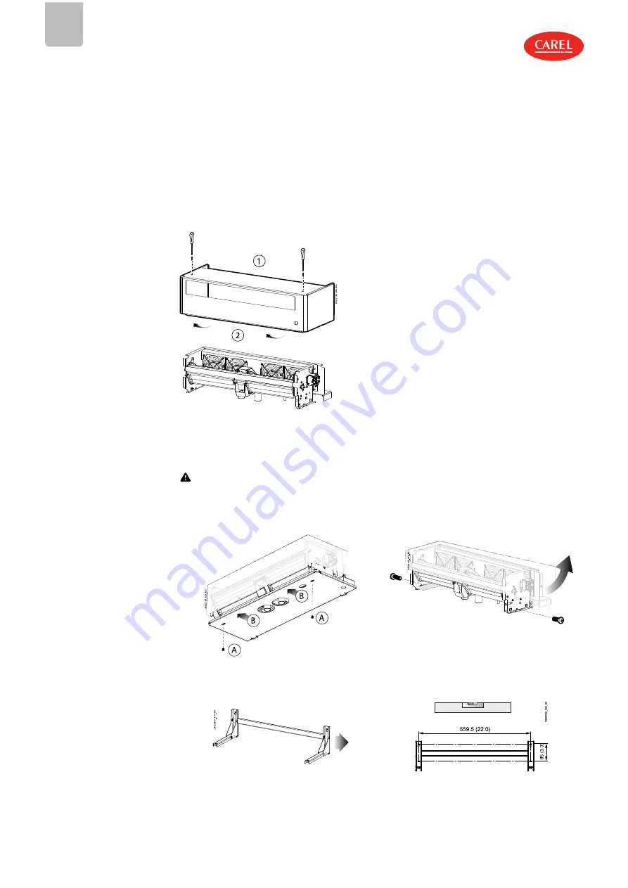
1. Sconnettere elettricamente la testata ventilante;
2. Svitare le 2 viti di fissaggio posizionate sulla superficie superiore del coperchio;
3. Estrarre il coperchio alzandolo con leggera rotazione in avanti per svincolarlo.

Fig.3.a

3.2
Montaggio

3.2.1 Montaggio a parete

Attenzione:

montare la testata ventilante solo su parete in muratura.

Fissaggio della testata ventilante al supporto

Procedura:

Fig.3.b

Fig.3.c

1. Rimuovere il coperchio (vedere par. precedente). Togliere
le viti (A) e rimuovere il fondo (B).

2. Rimuovere le viti ed estrarre il supporto dalla testata.

Fig.3.d

Fig.3.e

12

  |  3. Montaggio

VRDX030222195 rel. 1.2  – 22.03.2019

Summary of Contents for VRDXL00001

Page 1: ...MANUALE D USO USER MANUAL VRDXL00001 030222195 ITA ENG Up to date version available on www carel com VRDXL00001 Testata ventilante Steam blower ENG ITA ...

Page 2: ......

Page 3: ... bambini e animali l Non installare e utilizzare il prodotto nelle vicinanze di oggetti che possono danneggiarsi a contatto con l acqua o condensa d acqua CAREL declina ogni responsabilità per danni conseguiti o diretti a seguito di perdite d acqua dell umidificatore l Non utilizzare prodotti chimici corrosivi solventi o detergenti aggressivi per pulire le parti Interne ed esterne dell umidificato...

Page 4: ...l uso inteso tutte le informazioni contenute in questo manuale e in particolare le istruzioni di sicurezza devono essere osservate scupolosamente l Questo apparecchio può essere utilizzato da bambini di età superiore a 8 anni e da persone con ridotte capacità fisiche sensoriali o mentali o mancanza di esperienza solo se supervisionati e istruiti riguardo all uso sicuro dell apparecchio e ai rischi...

Page 5: ...NE AL MONTAGGIO 10 2 1 Prescrizioni 10 3 MONTAGGIO 12 3 1 Operazioni preliminari 12 3 2 Montaggio 12 4 MANUTENZIONE E PARTI DI RICAMBIO 14 4 1 Componenti 14 4 2 Sostituzione componenti 14 5 CARATTERISTICHE TECNICHE 16 VRDXL00001 030222195 rel 1 2 22 03 2019 5 ...

Page 6: ......

Page 7: ...e con Ø 30 mm 1 18 in 1 1 3 Accessori Cod Descrizione 1312368AXX Tubo condensa Ø int 9 mm 0 35 in 1312365AXX Tubo del vapore Ø int 30 mm 1 18 in 1312367AXX Tubo del vapore Ø int 40 mm 1 57 in Tab 1 c 1 1 4 Ricevimento identificazione Dopo aver ricevuto l apparecchio controllare l eventuale danneggiamento della scatola e se tutti i componenti sono stati consegnati Verificare dalla targhetta identif...

Page 8: ...consenso e i ventilatori si attivano L aria prelevata posteriormente fuoriesce mescolandosi con il vapore e favorisce l assorbimento in ambiente La testata ventilante può funzionare con due logiche differenti 1 indipendentemente dall umidificatore 2 gestita direttamente dall umidificatore c pHC Il controllo ritarda l avvio della testata dopo un tempo prestabilito Anche lo spegnimento può essere ri...

Page 9: ...zione delle 4 testate rimane esterna a 230 Vac Rimozione del ponticello Nota nel caso l umidificatore non contenga il controllo c pHC rimuovere il ponticello L accensione della testata ventilante avviene in base all attivazione del termostato interno Svitare le viti per rimuovere il ponticello P Fig 1 e La testata ventilante esce di fabbrica con il ponticello montato controllo della testata ventil...

Page 10: ...ti da CAREL tubi di altro materiale possono influenzare negativamente il funzionamento del sistema l il tubo del vapore deve essere sostenuto da supporti morsetti staffe in modo da non piegarsi e non gravare sull umidificatore Un tubo riscaldato ha maggiore probabilità di piegarsi l il raggio di curvatura minimo del tubo del vapore è 5 volte il diametro interno l il tubo del vapore deve avere una ...

Page 11: ...ve confluire in un sifone alto 200 mm il sifone deve trovarsi almeno 300 mm sotto l attacco della testata ventilante In alternativa il tubo della condensa può essere collegato all attacco della vasca di raccolta condensa posto nella parte superiore dell umidificatore l gli scarichi della condensa devono essere installati in tutti i punti più bassi e ogniqualvolta vi è un passaggio da posizione ori...

Page 12: ...ate sulla superficie superiore del coperchio 3 Estrarre il coperchio alzandolo con leggera rotazione in avanti per svincolarlo Fig 3 a 3 2 Montaggio 3 2 1 Montaggio a parete Attenzione montare la testata ventilante solo su parete in muratura Fissaggio della testata ventilante al supporto Procedura Fig 3 b Fig 3 c 1 Rimuovere il coperchio vedere par precedente Togliere le viti A e rimuovere il fond...

Page 13: ...ringere le fascette per fissare i tubi del vapore B e il tubo condensa Collegare alla morsettiera il cavo dell alimentazione elettrica Infine rimontare il coperchio C Nota effettuare il collegamento del tubo vapore del tubo condensa e del cavo elettrico seguendo le avvertenze del cap Preparazione al montaggio ITA VRDXL00001 030222195 rel 1 2 22 03 2019 3 Montaggio 13 ...

Page 14: ...i effettuare qualunque operazione l togliere l alimentazione elettrica all umidificatore portando l interruttore generale dell impianto su spento OFF l rimuovere il coperchio della testata ventilante vedere paragrafo precedente l sostituire il componente guasto l terminate le operazioni di manutenzione rimontare i componenti operando nel senso inverso ripetto a quanto descritto 4 2 1 Ventilatore D...

Page 15: ...zione l Verificare il fusibile l Verificare che l umidificatore funzioni e vi sia richiesta di umidità Ventilatore non funziona ma l umidificatore sta generando vapore l Linea vapore installata in modo errato non arriva sufficiente vapore l Termostato bloccato l Testata ventilante non alimentata l Fusibile guasto l Verificare che il tubo vapore non sia piegato l Sifone installato correttamente non...

Page 16: ...1 Tabelle accoppiamento umidificatori humiSteam uscita umidificatore ø mm 22 30 0 9 1 2 30 1 2 40 1 6 2x 40 1 6 4x 40 4x 1 6 capacità umidificatore kg h 1 3 5 8 9 10 15 18 25 35 45 65 90 130 umidificatore UE001 UE003 UE005 UE008 UE009 UE010 UE015 UE018 UE025 UE035 UE045 UE065 UE090 UE130 VSDU0A0003 18kg h 1 1 1 1 1 1 1 1 VRDXL00001 45kg h 1 1 1 2 2 4 Tab 5 a heaterSteam uscita umidificatore ø mm 3...

Page 17: ...th water or condensate CAREL declines all liability for direct or indirect damage following water leaks from the humidifier l Do not use corrosive chemicals solvents or aggressive detergents to clean the inside and outside parts of the humidifier unless specifically indicated in the user manual l Do not drop hit or shake the humidifier as the inside parts and the linings may be irreparably damaged...

Page 18: ...the age of 8 and by persons with reduced physical sensory or mental capabilities or lack of experience if they have been given supervision or instruction concerning use of the appliance in a safe way l Children must not play with the appliance l Cleaning and maintenance must not be carried out by children unless they are supervised by an adult Fundamental safety rules Before carrying out any maint...

Page 19: ...ARING FOR ASSEMBLY 10 2 1 Requirements 10 3 ASSEMBLY 12 3 1 Preliminary operations 12 3 2 Assembly 12 4 MAINTENANCE AND SPARE PARTS 14 4 1 Components 14 4 2 Component replacement 14 5 TECHNICAL SPECIFICATIONS 16 VRDXL00001 030222195 rel 1 2 22 03 2019 5 ...

Page 20: ......

Page 21: ...ts with ID 30 mm 1 18in 1 1 3 Accessories P N Description 1312368AXX Condensate hose ID 9 mm 0 35 in 1312365AXX Steam hose ID 30 mm 1 18 in 1312367AXX Steam hose ID 40 mm 1 57 in Tab 1 c 1 1 4 Receiving identification After having received the appliance check that the box is not damaged and all of the components have been delivered Verify on the identification rating plate that the model is suitab...

Page 22: ...troller gives the signal and the fans are activated The air taken in from the rear is mixed with steam before being delivered into the room where it is easily absorbed The blower features two different types of operating logic 1 independent of the humidifier 2 managed directly by the humidifier c pHC The controller delays blower activation for a set time Deactivation can also be delayed to allow t...

Page 23: ...ontroller The 230 Vac power supply to the 4 steam blowers remains external Removing the jumper Note If the humidifier is not fitted with the c pHC controller remove the jumper The blower will be activated by the built in thermostat Unscrew the screws to remove the jumper P Fig 1 e The blower leaves the factory with the jumper inserted blower managed by the c pHC controller on the humidifier ENG VR...

Page 24: ...om other materials may adversely affect operation of the system l the steam hose must be secured by supports clamps brackets so that it does not bend and does not weigh on the humidifier A hot hose is more likely to bend l the minimum radius of curvature of the steam hose is 5 times the inside diameter l the steam hose must have a minimum slope in order to drain condensate back to the humidifier i...

Page 25: ...rd slope and must flow into a 200 mm high drain trap the drain trap must be at least 300 mm below the connection to the blower l condensate drains must be installed at all the lowest points and wherever the drain line goes from horizontal to vertical The drain line must be connected to a T connector and have a minimum downward slope The drain trap must be at least 300 mm below the connection l mak...

Page 26: ...by slightly turning it forward to release it Fig 3 a 3 2 Assembly 3 2 1 Wall mounting Important mount the blower only on masonry walls Fixing the blower to the support Procedure Fig 3 b Fig 3 c 1 Remove the cover see previous paragraph Unscrew the screws A and remove the bottom panel B 2 Remove the screws and extract the support from the blower Fig 3 d Fig 3 e 3 Make the holes in the wall to fix t...

Page 27: ...n condensate hose Connect the power supply cable to the terminal block At the end mount the cover C again Note install the steam hose the condensate hose and the power cable following the steps described in the previous paragraph and the notes in chap Preparing for assembly ENG VRDXL00001 030222195 rel 1 2 22 03 2019 3 Assembly 13 ...

Page 28: ...y qualified personnel Important before proceeding l disconnect power to the humidifier by turning the main system switch to OFF l remove the cover from the blower see the previous paragraph l replace the faulty component l once having completed maintenance reassemble the components by working in reverse to the steps described above 4 2 1 Fan After having removed the blower cover see chap Assembly ...

Page 29: ...ed l Faulty fan l Check power supply l Check fuse l Make sure that the humidifier is operating and humidity production is required The fan is not working but the humidifier is generating steam l Steam line installed incorrectly not enough steam reaches the blower l Thermostat stuck l The blower is not powered l Faulty fuse l Make sure that the steam hose is not bent l Drain trap installed correctl...

Page 30: ... 2 No 104 R1999 5 0 1 Humidifier connection tables humiSteam humidifier outlet ø mm 22 30 0 9 1 2 30 1 2 40 1 6 2x 40 1 6 4x 40 4x 1 6 humidifier capacity kg h 1 3 5 8 9 10 15 18 25 35 45 65 90 130 humidifier UE001 UE003 UE005 UE008 UE009 UE010 UE015 UE018 UE025 UE035 UE045 UE065 UE090 UE130 VSDU0A0003 18kg h 1 1 1 1 1 1 1 1 VRDXL00001 45kg h 1 1 1 2 2 4 Tab 5 a heaterSteam humidifier outlet ø mm ...

Page 31: ...ENG VRDXL00001 030222195 rel 1 2 22 03 2019 17 ...

Page 32: ...ria 11 35020 Brugine Padova Italy Tel 39 049 9716611 Fax 39 049 9716600 email carel carel com www carel com VRDXL00001 030222195 rel 1 2 22 03 2019 CAREL non si assume alcuna responsabilità per possibili errori in questo manuale CAREL si riserva il diritto di modificare i propri prodotti senza preavviso ...

Reviews: