RC
ㅴ㵘㯖㘘
/
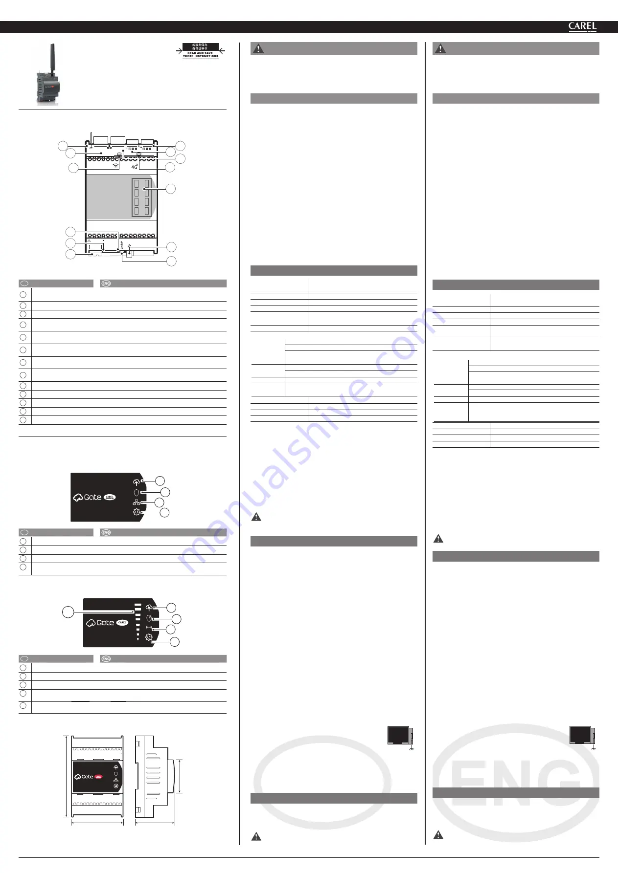
CONNECTOR’S DESCRIPTION
G
G0
2
24V~/24V
20VA/9W
LAN
FIELD
6
7
9
11
13
8
1
10
12
4
2
5
3
㵝㏞
/
key:
RC
说明
Description
1
⮈䊕ㅴ㵘
[G(+), G0(-)] 24Vac/Vdc
Power supply connector [G(+), G0(-)] 24Vac/Vdc
2
LED
㵉⮈᷉㔭㩌᷊
/
LED power-on (green)
3
䄵㲌㶙㾦⼦
Led/
Ethernet signal Led
4
㡕䇤㑺㬒
IP / WPS /
䊧Ⱜ㑍ㅴネ⥊㆗㬫䇤䇻
2G/4G
⟇
Enable temporary IP / WPS / connection check to cloud (only for 2G/4G mod.)
5
USB
⢋䓝䑘〛ㅴ㋻᷍
type A
ㅴ㋻᷍䇤䇻㪞ミ⼮㻣䊹㦶䐟㸥ミ
USB standard HOST Port, type A connector, upgrading FW and log files downloading
6
RS485
⺃⮈ⷕ㏌㵉䁗㋻
/
RS485 serial opto-isolated;(
⡄㒕䄵⡙ㅌ㎕㬚䇤
/ R
eserved for
future use)
7
RS485
⳨⺃⮈ⷕ㏌㵉䁗㋻
/
RS485 serial not opto-isolated; (
䇤䇻㑍ㅴ56㪉⡙⭥㶙㕈
Used for the connection to the network of RS485 devices)
8
FIELD
䄵㲌㶙
/
FIELD Ethernet;
(
䇤䇻ⳤ㸫㚻⤠㞅䐤䄔㘇
/
Used to access the internal configuration pages)
9
LAN
䄵㲌㶙
/
LAN Ethernet;
10
䇤䇻㠢⡯䄵㲌㶙Ⱜ㋻ㅴ⭹⭥㌍ㅴⰬ䓴
/
Faston for shield ethernet port earth connection
11
2G/4G
㳍㼀ㅴ㵘
/
2G/4G Antenna connector (*)
12
Wi-Fi
㳍㼀ㅴ㵘
/
Wi-Fi Antenna connector (*)
13
LED
䓽㵝
/
LED synoptic
(*)
㋪䄵䁂䋒
Wi-Fi
⼮
2G/4G
䎃㑞䁂㼏᷍䄵⢄㼁⿆⡙䇤᱄
/ The two options Wi-Fi and 2G /
4G are available as an alternative to the other
LED
⢋㬗⼍䅆
/
LEDS MEANINGS
䄵㲌㶙⟇
/
Ethernet version
IP
A
C
D
B
RC
说明
Description
A
䊧㑍ㅴ
/
Cloud connection
B
IP
⭹䐘㞅
/
IP address assigned
C
䄵㲌㶙㑍ㅴ
/
Ethernet connection
D
㧎ミ䅞㤇ᷛ㩢㯙ᷛ䎞䊻ゴ䊹ᷜ㸩Ⰹᷛ䎞䊻䊬㾱
Software engine: flashing: loading; steady: functioning
䄧Ⱀ䊧㶙⟇᷉
Wi-Fi
〓
2G/4G
⟇᷊
/
CloudGate Mobile (wi-fi or 2G/4G) vers.
A
C
D
B
E
RC
说明
Description
A
䊧㑍ㅴ
/
Cloud connection
B
IP
⭹䐘㞅
/
IP address assigned
C
㸿㼀⮈㑍ㅴ
/
Radio connection
D
㧎ミ䅞㤇ᷛ㩢㯙ᷛ䎞䊻ゴ䊹ᷜ㸩Ⰹᷛ䎞䊻䊬㾱
Software engine: flashing: loading; steady: functioning
E
㸿㼀⮈㾦⼦㣠Ⱙᷛ㔭㩌
Led
ᷛ
2G/4G
ᷜ㩌
Led
ᷛ
Wi-Fi
Radio signal strength: green Led: 2G/4G; yellow Led: Wi-Fi
⨀⫈
/
DIMENSIONS
70
60
110
45
IP
DIN
➓䓑ᷛⷚ㈾
DIN 43880
⼮
IEC EN 50022
᷍⡟㪉⡙➓䓑䊻
DIN
⭝⺍㩰ᷜ
DIN mounting:
fi tted on DIN rail in accordance with DIN 43880 and IEC EN 50022;
"CloudGate"
+0500150EZ - rel. 1.2 - 24.09.2021
䊧㶙ᷛ䔊䓑⧭㿓
/
C
loudGate:
Assembly procedure
㈐
䐜㚽䇪㬼⽔ⴟ㹒㦬䊒᷉⼰ⷒ➓䓑㦬䊒᷊➓䓑⡟㪉⡙᷍ⶤ㦬䊒⡹
㿌㈎⺞㬫⭒ゝ㭖㞁䁖᷍㉀䇱㼁㈎䂊᷍⤃㣳䐋㼟㞅䐤⫎㹔㋪㚽
䅞㡑⭥㸄㻶᱄
䄜⟄㯖㘘
䐕㾱㦯⼯⤺䔘䐏㣑᷍㤌ネ⥊
CloudGate
䊧㶙㪉⡙⟝㬨ⴒ⟝⼍ᷛ
ⶤ㪉⡙⡟㳆ᷜ
ⰵ䇻㸿㼀⟇⡟ᷛ⫙㳍㼀᷉
Wi-Fi
〓
2G/4G
㏁㾮᷊᱄ⰵ䇻⫙㯌㸿㼀
⮈⭥㾮⼦᷍⡹㿌㰇㞅㑞㳍㼀᱄
ゝ㭖㸥ミᷜ
Ⱜ䓴㲸ミ⼮㑞
120Ω485
㼀⮈䔉㡘᱄
㤌㹑ㅌ⡟⥛㠘➓䓑䊻㉀䇱䄵㻣㲹䎘⭥㈔䐱ᷛ
㤌㹑ㅌ⡟⥛㠘➓䓑䊻㉀䇱䄵㻣㲹䎘⭥㈔䐱ᷛ
⫇䊻㣠㑳䎒Ⱀ〓㞗䓓ᷜ
⫇䊻㣠㑳䎒Ⱀ〓㞗䓓ᷜ
⫇䊻㣠⮈⪦⼮〓㪅㠖ⶪ㦦᷉ベ䇻⪬᷍㤌⡽㘃ㅌⶤ㪉⡙➓䓑䊻ⳃ
㪅㳍㼀㆝᷊ᷜ
⡊㔗䊻䐒㪅䂕⺃㻣䄵ゑㅴ⪆䄜⟄䊋㯹ᷜ
㬳㸣⫇䊻㈿⫔⼮䁙㯺⤉Ⱀᷜ
⫇䊻⡍䍉㹐〓䄸㦝㡙㳆」⼰㹐⭥㈔᱄
“
㸿㼀⮈
”
⟇⭥➓䓑㈐㾦㻃
•
“
㸿㼀⮈
”
⟇⭥➓䓑㈐㾦㻃
ㅌ㳍㼀⳦䐤䊻㆑㭕䇓ミ㶃⤠᱄
ゝ㭖⺇ⳗ
⮈䊕
⪴
G
⭞
G0
ᷛ
24 Vac +10%/-15% 50/60 Hz, 24 Vdc
+5% /-5%
㭅㧌⹇㔫
䔏⫔
9W
⤺䔘㳖ミ
-40~60 °C, 90% r.H
⳨㏅㛞
⪃⫇㳖ミ
-40~70 °C, 90% r.H
⳨㏅㛞
⪏㾱Ⱜ㋻
1
RS485
⺃⮈ⷕ㏌䑘Ⱜ㋻
- 1
RS485
⳨⺃⮈ⷕ
㏌䑘Ⱜ㋻
⮈⧹᷉㚻⤠᷊
“
㝇㋼
”
㾮囏⮈⧹᷍
BR2032
᷍
3 Vdc
᷍⤜㋪⨅⮈
㦰䐅䄋㤔
RED:
- WIFI
- 2G/4G
EN 301 489-1
EN 301 489-17 Ver. 3.1.1 - EN 300 328 Ver. 2.1.1
EN 301 489-52 Ver. 1.1.0 - EN 301 511 Ver. 12.5.1 -
EN 301 908-1 Ver. 11.1.1
FCC:
- WIFI+2G/4G:
FCC
⭻
15
⤠⭻
B
䓴⤠᷍
ICES003
FCC15.31 (k)
⤠
- ANSI C95.1. MPE - RSS-102. MPE
➓㦌
:
60950; 62368
ANATEL
ⶤ㪉⡙⤜⭤㆙㾱䇱⼇ⶪ㦦⡄⿅᷍䊻㈎⺞䎞㬞㬻㦉⭥㻖
㵔䐱⤜。䋍⧪ⶪ㦦᱄
⨀⫈
4 DIN
㚄㌊
= 70x110x60 mm
㸼㦟⭩
2
ⷚ㈾
EN60950-1 / EN62368-1
ⳡ⿅⭩
IP10
㶃㋨⤥㑰
㧞䊋⹓㈼㹐
㵉⮈㬒㤌㹑⫓㋋㪉⡙᱄
⮈䊕
⡟⥛㠘⭥⮈䊕䐜㚽㑍ㅴ䊻
G
⼮
G0
䐏ヅ᱄
䔏⫔⧅Ⱙ㸋
5
㗸᱄
㧈⺜㬚䇤ㅜ㒘⮈䊕⹊⮈᷍㤌㬚䇤
2 24Vac
᷍
20 ......30VA
⭩⭥䓉
䇤➓㦌⢅䁚㡘᷍ⶤ⢅䁚㡘㉀䇱Ⱝ㔘⡄⿅⼮⺞䊹⡄⿅᷍㣳ⱟ⿹㔘
⤜ㅴ⭹᱄
㧈⺜⤪䇤䐒㒘⮈䊕⹊⮈᷍㚨㗕㤌㬚䇤
PGTA00TRX0
᱃
100 /
230Vac-24Vdc
⮈䊕᷉
10W±2
᷆
1 DIN
㚄㌊᷍䔏⭮㸣Ⱙ
-25°C
᷊᱄ㅌ
䎞れ㑍ㅴ⭞
G
᷍ㅌれ㑍ㅴ⭞
G0
᱄
注意
ᷛ⪏㾱㑍ㅴ⼮⮈䊕㬚䇤⤜㵍⭥⮈㎣᱄
㵉䁗㼀
RS485
㵉䁗㼀
䔏⫔⧅Ⱙ⤜⭤⧍⺞P᷍ⰵ䇻䔏⫔P⭥㼀㔘᷍㵉⺞$:*㠢
⡯⮈㎣᷍ⰵ䇻䔏⫔P⭥㼀㔘᷍㵉⺞$:*᷍ⰵ䇻䔏⫔P⭥
㼀㔘᷍㵉⺞$:*㆙㾱㠢⡯᷍㠢⡯⥄䇇ㅴ⭹㣳⤜ㅴ⭹᱄ ゕ㬚⧅
Ⱙ⧍⺞㗸᷍䄓⡹㿌㑍ㅴ⭞㶙㕈⭥⭻䄜⼮䔏⽔䄜㪉⡙⭥
:⭥Ą䐶Ⱜ⮈䔉᱄ ⥛㠘㰇⭥⮈䔉㡘䇇㑍ㅴ䊻⪏㾱⼮Ⱜ䓴
䐏ヅᷛ
⡟⥛㠘㰇⭥⮈䔉㡘䇇㑍ㅴ䊻⪏㾱᷉䎞᷊䈌᷊᷉Ⱜ䓴䐏
ヅᷛ
⥍れ㾵᷉
+
᷉䎞᷊᱃
-
᷊᷉᱃ㅴ⭹᷊
㤌㹑䊻㼀㔘〓㾨㾯㑍ㅴ䐱䔗䐈ᷜ
⡽㘃ㅌ㼀㔘㠭㪉䊻⮈䊕㼀㆝᱄
㸋㑬㳂ⷀ㋹䐧㡘ⰵ⮈⪦ⶪ㦦⭥⭷㋚㑇᷍⪏㾱㑍ㅴ⮈㎣⡹㿌㬚䇤㯌
ㅫ㠢⡯⮈㎣᱃㑞㾟〓㧞㾟㯌ㅫ⮈㎣᷍㉀㳆㦂㉗䇻⪏㾱㑍ㅴ⭥㉙䊖
㾵᱄
䇇㬫䇤䄵㻣⺇䋓ᷛ
㧈⺜⪏㾱Ⱜ㋻䄲䈌⮈䊕᷉⹇㚽㩰᷊㉙䊖᷍㚨㗕䊻⪏㾱⮈㎣䐱᷍
㿉䄋㬚䇤⭻㧞ⷚ㼀䔘㸋㋹䐧㡘⭥㵉䇤⤯㋝㼀㔘ᷜ
㧈⺜⪏㾱Ⱜ㋻⤜㬨⺃⮈ⷕ㏌Ⱜ㋻᷍⤃㣳䄲㈎⫇䊻⹌䇤⤯㋝㼀
㔘᷍㚨㗕⤜㿉䄋㠭㪉⭻㧞ⷚ㼀᱄
RJ45
䄵㲌㶙㼀
㬚䇤
100
㗸
5e
㏁
SFTP
㠢⡯⮈㎣᱄ⰵ㠢⡯䄵㲌㶙⮈㎣㆙
㾱ㅴ⭹᷉⹇㚽㑍ㅴ᷊㬒᷍㤌㬚䇤㧈㵝㰚㬟⭥
6.3
⼢㗸
⧱⥆㬞㌍ㅴⰬ䓴᱄
ⶤ⥛㠘⺊㸋ⱟ㏁᷍⭌㬨ㅴ⭹᷉⹇㚽㾵᷊㠢⡯⮈㎣㉀䇱䄜㌍ㅴⰬ
䓴᱄ⶤ㑍ㅴ㋪䄵䐒ㅴㅴ⭹᷉⡄⿅᷊〓䎀䈌㡅㰝㶃⤠⮈䊕⭥㸄㻶⮈
䁚㋋ㅴ⭹᷉⹇㚽᷊᱄
➓䓑
㸋㑬⡄⿅⤺䔘䊒⼮㑍ㅴ⟆᷍䊻䐕㾱㦯⼯⤺䔘䐏㣑᷍㤌㻩ⰰ㋋⮈
䊕᱄㧈⺜⡟⥛㠘㬨䇪㯽㑰䐧⧪⭥᷍㚨㗕⡹㿌ㅌ㡅➓䓑䊻⮈㡙㘇⟆
㚻᷍⤃㬚䇤㋪㦝㾵⭩㸋
5VA
⭥⤥㑰᱄
㆗㋪㑍ㅴ⥛㠘⟝䓑䐱⭥㬳㚻㳍㼀᱄
WA
R
NING
This appliance must only be installed by service personnel with
suitable technical training and experience and who are aware
of the dangers they may be exposed to in the event of incorrect
confi guration (qualifi ed installers).
GENE
R
AL NOTE
Before performing any operations, check that the CloudGate contains:
1. the device itself;
2. for wireless version: an antenna ( Wi-Fi or 2G/4G type);
3. technical documents;
4. terminals kit and two resistors 120Ω for the end of the serial line.
Do not install products in environments with the following
characteristics:
•
relative humidity greater than the value specifi ed in the technical
specifi cations;
•
strong vibrations or knocks;
•
exposure to aggressive and polluting atmospheres (e.g.: sulphur and
ammonia fumes, saline mist, smoke) so as to avoid corrosion and/or
oxidation;
•
strong magnetic and/or radio frequency interference (therefore avoid
installing the units near transmitting antennae);
•
exposure to direct sunlight and to the elements in general;
•
large and rapid fl uctuations in the room temperature;
•
environments where explosives or mixes of fl ammable gases are present.
Installation warnings for Radio models
•
Before installing the product make sure the area is suffi
ciently
covered by a 2G/4G - Wi-Fi signal, if the model to be used includes
radio connectivity;
•
locate the antenna outside metal hardware.
TE
C
HNI
C
AL SPE
C
IFI
C
ATIONS
Power supply
from G to G0: 24 Vac +10%/-15% 50/60 Hz, 24 Vdc
+5% /-5%
Input power
9W Max
Operating conditions
-40T60 °C, 90% U.R. non-condensing
Storage conditions
-40T70 °C, 90% U.R. non-condensing
Serial Ports
1 RS485 Master opto-isolated- 1 RS485 Master
non opto-isolated
Battery (internal)
Lithium “button” type, BR2032, 3 Vdc, NON
rechargeable
Certifi cation requirements
RED:
- WIFI
- 2G/4G
EN 301 489-1
EN 301 489-17 Ver. 3.1.1 - EN 300 328 Ver. 2.1.1
EN 301 489-52 Ver. 1.1.0 - EN 301 511 Ver. 12.5.1 -
EN 301 908-1 Ver. 11.1.1
FCC:
- WIFI+2G/4G
FCC Part 15 Subpart B, ICES003
FCC Part 15.31 (k) - ANSI C95.1. MPE - RSS-102. MPE
Safety:
60950; 62368
ANATEL
This equipment is not entitled to protection against
harmful interference and may not cause interference in
duly authorized systems.
Dimensions
4 DIN module = 70x110x60 mm
Pollution degree
2 according to EN60950-1 / EN62368-1
Index of protection
IP10
Case material
tecnopolymer
Do not open the device when powered.
Power supply
•
Power supply to the product must only be connected between G
and G0
•
Maximum length =5 m.
•
If AC powered, use a dedicated safety transformer rated in Class 2
24Vac, 20...30VA,
protected against short-circuits and overload
,
without
secondary must be earthed connected
.
•
If direct current powered use PGTA00TRX0 power supply, 100/230Vac-
24Vdc (10W ±2% 1 DIN-module, Minimum Temperature = -25°C).
Connect the positive pole to G and negative pole to G0.
CAUTION:
use separate cables for serial connections and power supply.
C
OMMUNI
C
ATION LINES
RS485 communication lines
The maximum length must not be over 1000m, via AWG24 shielded
cable for lines max 100m, AWG22 for lines max 500m, AWG20 for lines
max 1000m lenght,
with screen connection to earth and not to GND
.
The 120Ω terminal resistors, 1/4W into the fi rst and the last devices of
the network, must be connected even if the lenght exceeds 100 meters.
The resistors, included in the product, are to be connected between the
and - terminals:
•
observe the polarity (+.-,GND);
•
do not make branches in the line or star connections;
•
avoid laying the line near power cables.
To improve immunity of the controller to electromagnetic disturbance,
the serial connection cable must be twisted pair shielded, twisted two-
or three-wire depending on the insulation of the serial connection.
The following rule applies:
•
if the serial port is insulated (functionally) from the power supply, a
third wire is required in the serial cable to act as a common reference
for the controllers;
•
if the serial port is not optically-isolated and the common reference is
already present, the third wire is not needed.
RJ45 Ethernet Linee
Use shielded cables 100 m Cat.5e SFTP. To connect earth
the screen ethernet cable (functional connection), use a
female Faston 6,3mm, as indicated inthe fi gure.
The product is class II classifi ed, but there is a faston for the earth
connection (functional) shiel cable. The connection could be directed
to earth (protection) or, earth (functional) separated by dangerous
voltages from to other external power supplies.
MOUNTING
To safeguard operators and the boards, disconnect power before
performing any operations. The product must be installed inside an
electrical panel; if it is made of plastic material use one with fl ammability
rating of 5VA.
Connect only the indoor antennas in the package.


