background image


pAD +030220873 - rel. 1.2 18.01.2013  

26


Further information 

1. 

A power supply other than the one specified may 
seriously damage the system. 

2. 

Important: if the device is used in a way that is not 
specified by the manufacturer, the protection of the 
device may be compromised. 

3. 

Use cable ends suitable for the corresponding 
terminals. Loosen each screw and insert the cable 
ends, then tighten the screws. When the operation is 
completed, slightly tug the cables to check they are 
sufficiently tight. 

4. 

To clean the display use a soft cloth. Do not use 
water. 

5. 

Operation at particularly low temperatures may cause 
a visible decline in the response speed of the display. 

This should be considered normal and does not 
indicate a malfunction. 

6. 

The terminal must be fastened to the wall in such a 
way as to allow the recirculation of air through the slits 
on the rear shell. Avoid places where the room 
temperature measurement may be altered, for 
example outside walls, near doors leading to the 
outside or in direct sunlight. 

7. 

Separate the cables running to the device from cables 
that supply inductive loads and power cables, so as to 
avoid possible electromagnetic disturbance. Never 
use the same conduits for the power cables (including 
other electrical cables) and serial communication 
cables. Do not install the communication cables in the 
immediate vicinity of power devices (contactors, 
circuit breakers or similar). 


4.


CONFIGURATION AND STARTING 


When started, the pAD, after having completed the initialisation procedure, shows 

 in the temperature display for a few seconds, indicating that it is researching 

for the pCO controller connected to the data line. 


To access the parameters, proceed as follows: 

4.


press the UP button; 

5.


within three seconds press the DOWN button; 

6.


when “

PAr

” is displayed in the main area, release the DOWN 

button while holding the UP button and press KEY6 within 
three seconds


Procedure for setting the parameters  
In this mode, all the symbols are off, except for the following fields: 

 indicates the value of the parameter currently being set; 

 indicates the name of the parameter currently being set. 

To set the parameters, proceed as follows: 

5.


The 

 field flashes. Use the UP/DOWN buttons to select the 

parameter to be set, then press KEY6 or (PRG). 

6.


The 

 field flashes. Use the UP/DOWN buttons to set the desired 

value, then press KEY6. 

7.


Repeat the actions from point 1 until completing all the desired operations 

8.


To exit the parameter setting procedure, saving the changes made, simply 
hold KEY6 for 3 seconds. 

To exit the parameter setting procedure without saving the changes, simply wait 60 
seconds from when the last button was pressed, or press KEY4; 45 seconds after the last 
button was pressed the name or the value of the parameter flashes. 
If the communication parameters are changed (Ad01 and/or Br01), communication will 
be re-initialised by the pAD. 
The table below describes the meaning of the operating parameters. 


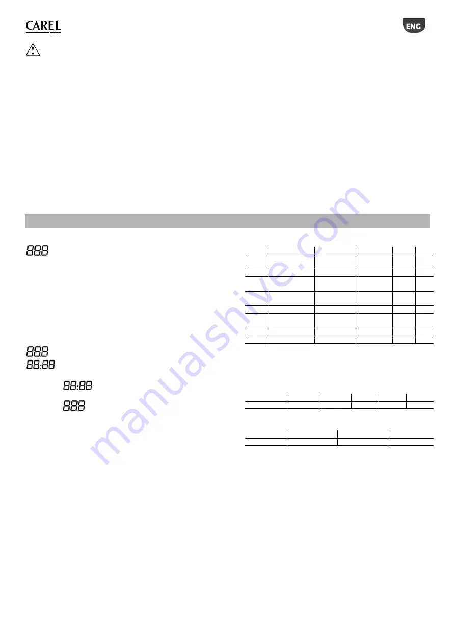
Name Description 

Min 

Max 

UOM  Def. 

Ad01 

pAD pLAN 
network address 

32 

Ad02 *

Supervisor address 1 

255 

Br01 

pLAN baud rate 

0 (62.5 Kbps) 

1  (115.2 
kbps) - 

Br02 * 

Supervisor baud 
rate 0  4 

En01 

Enable buzzer 

Pc01 

Room probe 
calibration -9.9 

+9.9  °C/°F 

0.0 

rEL 

Firmware release 

Prot * 

Select protocol 

indicates the parameters that are only available in the versions that support the 

Carel/Modbus protocols. 
 
 
In the models configured for the Carel/Modbus protocols, Supervisor baud rate values 
correspond to the following parameter settings: 
 

Br02 

0 1 2 

Baud rate 

1200 2400 4800 

9600 

19200 


The protocol used is set by parameter 

Prot

, which can have the following values: 

Prot 

1 2 3 

protocol pLAN 

Carel 

Modbus 


Summary of Contents for ADPB003000

Page 1: ...pAD Ambient Display terminal User manual...

Page 2: ......

Page 3: ......

Page 4: ...CAREL CAREL CAREL CAREL www carel com CAREL CAREL CAREL CAREL CAREL CAREL CAREL CAREL www carel com CAREL CAREL 2002 96 EC 27 2003 13 2005...

Page 5: ...1 9 1 1 pAD 9 1 2 pAD 9 1 3 pAD 9 2 10 2 1 10 2 2 10 2 3 10 3 11 3 1 11 3 2 11 3 3 11 4 12 5 13 5 1 13 5 2 13 5 3 13 5 4 14 5 5 14 5 6 14 5 7 14 5 8 14 5 9 15 5 10 15 6 16 7 17...

Page 6: ...6...

Page 7: ...013 9 1 1 1 pAD pAD pCO pAD pLAN RS485 1 2 pAD pAD 3 pCO pAD pCO pAD 1 3 pAD ADPB003000 pAD NTC ADPB003010 pAD NTC ADPC003000 pAD NTC ADPC003010 pAD NTC ADPG003000 pAD NTC ADPG003010 pAD NTC ADPH00300...

Page 8: ...30220873 rel 1 2 18 01 2013 10 2 2 1 1 2 3 4 5 6 7 8 9 10 11 12 13 14 2 2 KEY1 KEY6 1 KEY 1 POWER 2 mode KEY 2 MODE 3 KEY 3 HUM 2 4 KEY 4 NIGHT 5 KEY 5 CLOCK 1 6 KEY 6 TEMP 7 8 1 2 ADPC ADPG ADPH 2 3...

Page 9: ...pAD 030220873 rel 1 2 18 01 2013 11 3 3 1 pAD CEI C 431 IEC 670 3 2 G G0 2 0 5 1 5 2 250 mAT G 2 4 G0 pAD G0 G0 G pAD pAD pAD 3 3 RS485 3 AWG20 22 500 90 5 pLAN RS485 pLAN 32 30 pAD Carel Modbus RS485...

Page 10: ...PRG 2 KEY6 3 1 4 KEY6 3 60 KEY4 45 Ad01 Br01 pAD Ad01 pAD pLAN 1 32 2 Ad02 1 255 1 Br01 pLAN 0 62 5 1 115 2 0 Br02 0 4 4 En01 0 1 1 Pc01 9 9 9 9 C F 0 0 rEL Prot 1 3 1 1 Carel Modbus Carel Modbus Br0...

Page 11: ...pAD 030220873 rel 1 2 18 01 2013 13 5 5 1 POWER ON pAD POWER pAD OFF POWER OFF OFF pAD POWER 3 pAD POWER pAD POWER 3 5 2 pAD MODE 5 3 pAD MODE...

Page 12: ...pAD 030220873 rel 1 2 18 01 2013 14 5 4 pAD pAD 3 pAD pCO pCO 5 5 pAD pAD MODE 5 6 pAD pAD MODE 5 7 pAD KEY 3 pAD 3 5 8 KEY4 1HR 3 9 1 1 2HR pAD KEY4 3 diff...

Page 13: ...5 0 0 10 0 C F 2 0 NIGHT 3 pCO OFF pAD pAD 5 9 pAD pAD 5 KEY5 rtc 0 23 0 59 day 0 7 1 2 pAD pCO pCO 5 10 2 2 1 HH 1 1 ACTION 2 HH 2 2 ACTION 1 HH 1 1 ACTION 2 HH 2 2 ACTION 1 3 17 18 1 5 2 0 23 3 4 OF...

Page 14: ...pAD 030220873 rel 1 2 18 01 2013 16 6 2 Alr oLn pLAN AtE Ahu pAD...

Page 15: ...1 2 18 01 2013 17 7 EN60730 1 24 Vac 15 50 60 70 1 5 31 Vdc 29 70 UL873 24 Vac 50 60 2 25 5 36 25 Vdc 2 1 RS485 2 0 50 C 10 85 20 70 C 0 85 2 A A IP30 100 C EN60703 1 3 1 2 pAD 1 0 5 1 5 2 2 C 10 83 5...

Page 16: ...pAD 030220873 rel 1 2 18 01 2013 18...

Page 17: ......

Page 18: ...comply with the temperature and humidity limits specified in the manual Do not attempt to open the device in any way other than described in the manual Do not drop hit or shake the device as the inter...

Page 19: ...sembly and installation instructions 25 3 2 Power supply connections 25 3 3 Serial interface 25 3 4 Installation warnings 25 4 CONFIGURATION AND STARTING 26 5 FUNCTIONS 27 5 1 Device ON STANDBY 27 5 2...

Page 20: ......

Page 21: ...e and humidity set point reading of temperature and or humidity sensors time band management manual and automatic heating cooling mode changeover manual and automatic fan speed setting 3 speed clock s...

Page 22: ...program Icon Name standard Function 1 KEY 1 POWER Switch the system on or to standby 2 mod e KEY 2 MODE Set the operating mode cooling heating auto manual dehumidify manual humidify 3 KEY 3 HUM 2 Set...

Page 23: ...ortant if a terminal of the power supply needs to be earthed use terminal G0 and NOT terminal G both on the pAD the other powered devices When pAD has a DC power supply the controllers connected via t...

Page 24: ...in three seconds press the DOWN button 6 when PAr is displayed in the main area release the DOWN button while holding the UP button and press KEY6 within three seconds Procedure for setting the parame...

Page 25: ...seconds until the main field on the display shows OFF all the symbols will be switched off pAD ON AND TIME BANDS ACTIVE the symbol is on to temporarily activate deactivate the operation of the system...

Page 26: ...by the controller application program 5 7 Setting the humidity set point To set the humidity set point in the zone controlled by the pAD terminal Press the button associated with the humidity set poin...

Page 27: ...first five days of the week Monday Friday 2 common time bands for the last two days Saturday Sunday Setting the times and the actions The time bands menu displays the following settings in sequence ti...

Page 28: ...alarm code every 2 seconds The meaning of the codes is shown below Alarm Meaning Alr Active alarm on the controller Shown while the alarm is active oLn Offline no communication between the device and...

Page 29: ...d structure A Index of protection IP30 Ball pressure test temperature on the plastic used for the case 100 C Classification according to protection against electric shock EN60703 1 3 to be integrated...

Page 30: ...pAD 030220873 rel 1 2 18 01 2013...

Page 31: ......

Page 32: ...CAREL INDUSTRIES HQs Via dell Industria 11 35020 Brugine Padova Italy Tel 39 049 9716611 Fax 39 049 9716600 http www carel com e mail carel carel com pAD 030220873 rel 1 2 18 04 2013...

Reviews: