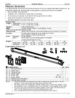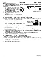
Carefree Installation
Manual L
ATITUDE
070005-001r12
7
S
WITCH
I
NSTALLATION
WARNING
Shock Hazard. Always disconnect battery or power source before
working on or around the electrical system.
NOTICE
To comply with 2018 NFPA 1192 RV Standard, Section 6.4.7, switches must be
mounted as follows:
For travel trailers and 5
th
wheels:
a)
Installed in a dedicated switch cabinet with a latching door;
or,
b)
Installed with the optional covered bezel available from Carefree; or,
c)
Installed in a cabinet with a latching door where the switch is protected and
CANNOT
be activated by
any items or cargo that may move or shift during transit;
or,
d) Installed with an interrupt circuit that disables awning extension when the vehicle is in motion (i.e. a relay
tied into the parking brake or ignition that disconnects the
BROWN
extend wire).
For motorized coaches (Class A, Class B or Class C):
a) Installed with an interrupt circuit that disables awning extension when the vehicle is in motion (i.e. a relay
tied into the parking brake or ignition that disconnects the
BROWN
extend wire or removes power from the
awning controls).
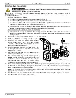
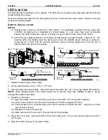
1. At the switch location cut a 2 5/16" [5.9cm) x 1 1/2" [3.8cm] hole.
2. Route the cable from the awning through the hole.
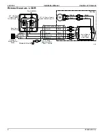
3. Terminate the three (3) 20awg wires (Brown,
Yellow, Gray) with .187, 18-20 awg female
terminals. Attach to the E
XTEND
/R
ETRACT
switch
as shown in the wiring diagram.
4. Terminate the RED wire from the cable with a .187,
14-16 awg female terminal. Attach to one terminal
of the ON/OFF switch.
5. Terminate the BLACK wire from the cable with a .25,
14-16 awg male terminal.
6. Run a minimum 14 awg wire to chassis ground.
Suitable ground would be the vehicle chassis or
conductive structure connected to the chassis.
Terminate the wire with .25, 14-16 awg female
terminal and connect to the black wire from the cable.
7. Run a minimum 14 awg wire from the power distribution panel (auxiliary battery circuit) or equivalent. The
circuit should be protected by a 15-amp fuse. Terminate the wire with a .187, 14-16 awg female terminal.
Attach to one terminal of the ON/OFF switch.
NOTE:
If the wire run is 30 feet or longer, use 12awg wire to prevent voltage drop. Use the
appropriate wire terminals for the wire size.
8. Push the wires and switches into the hole then attach the switch frame using four (4) #6 x 1/2" screws.
9. Snap the switch bezel over the switch frame.
1"
[2.5cm]
LCDR004
2.32"
[5.9cm]
1.5"
[3.8cm]
#6 x 1/2" Screw (x4)
RETRACT
ON
EXTEND
OFF
Awning Control
RETRACT
ON
EXTEND
Awning Control
OFF
Optional
Covered Bezel


