background image

Carefree Installation 

Manual  L

ATITUDE


070005-001r12 

Attaching the Canopy 

After the awning arms have been attached, it will be necessary to attach the canopy to the awning rail. 

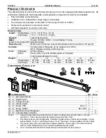
1.  Unwrap the plastic wrap from the roller tube and fabric.  DO NOT remove the tie straps holding the arms. 

2.  Unwrap the fabric over the roller tube and toward the awning rail. 

3.  Slip the fabric funnel onto the QuicKonnect. 

4. While holding the fabric, simultaneously slide the 

QuicKonnect into the awning rail and over the canopy. 

5.  Center the fabric and QuicKonnect with the roller tube. 

6.  Remove the funnel from the QuicKonnect. 

7.  Secure the fabric and QuicKonnect: 

7.1. Place one (1) #6 x 3/8" screw (a) through the 

QuicKonnect, fabric and polyrod approximately 1" in from 
the fabric edge. 

7.2. Place one (1) #6 x 3/8" screw (b) through the awning 

rail outside the end of the QuicKonnect (not through 
the QuicKonnect). 

7.3. On the other end of the QuicKonnect place one (1) #6 x 

3/8" screw (c) through the awning rail outside the end of the QuicKonnect (not through the QuicKonnect). 

7.4. Pull the fabric tight in the QuicKonnect then place one (1) #6 x 3/8" screw (d) through the QuicKonnect, 

fabric and polyrod approximately 1" in from the fabric edge. 

8.  While holding the roller tube, remove the ties holding the arms. 

9.  Allow the roller tube to extend until the fabric is taut. 

 NOTICE


The awning installation is not complete.  Except as directed, the awning should not 

be operated until completing all installation instructions including Adjusting the Arm Position.   

Secure the Awning 

Before operating the awning, it is necessary to finish securing the awning to the vehicle wall. 

1.  Open the awning approximately 18" to access the mounting plate.  To open, follow the directions in 

"Jumping the Motor" on page 3.  Do not close the awning except as noted in the instructions. 

NOTICE


Disconnect the battery after opening the awning to prevent unexpected awning motion. 

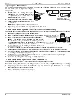
2.  Finish attaching the mounting plates using 

the same self-drilling 1/4 x 1" screws or 
the 1/4 x 2" lag screws used to initially 
mount the awning. 

3.  In the area shown, drill a 3/8" hole into the 

vehicle.  Deburr and clean the hole.  This is 
for the wire routing. 

4.  Route the motor cable from the arms and 

the LED harness from the canopy through 
the hole drilled previously.  After routing, seal the hole and wires with a quality silicone sealant. 

Remove the Temporary Assembly Pins 

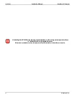
Two pins are inserted into the back of the left (idler) head for lateral stability during 
installation.  Using a pair of pliers, remove and discard the pins. 

 NOTICE


 Before operating the awning except as noted, the temporary 

pins must be removed.  Failure to remove the pins may cause the awning 
to not operate correctly. 

FL006b

Ø3/8" Hole
Into Vehicle Wall
for Wire Routing

Attach Plate with
Same Screws Used
Previously (x4)

Attach Plate with
Same Screws Used
Previously (x5)

Remove the

Cotter Pins

FL010

FL008

#6 x 3/8"
Screw (x4)

(a)

(b)

(c)

(d)

QuicKonnect

Fabric

Awning Rail

Funnel

QuicKonnect

Fabric

Awning Rail

Summary of Contents for LATITUDE

Page 1: ...e the product to not operate properly TABLE OF CONTENTS Product Overview 1 Component Checklist 1 Installation 2 Pre Installation Requirements 2 Mounting the Awning 2 Attaching the Canopy 3 Secure the Awning 3 Remove the Temporary Assembly Pins 3 Adjusting the Arm Position 4 Jumping the Motor when Direct Response is Installed 4 Jumping the Motor without Direct Response 4 Adjusting the Pitch 5 Switc...

Page 2: ...ION This is the safety alert symbol It is used to alert individuals to potential personal injury hazards Obey all safety messages that follow this symbol to avoid possible personal injury or death WARNING Indicates a hazardous situation which if not avoided could result in death or serious bodily injury CAUTION Indicates a hazardous situation which if not avoided may result in minor or moderate bo...

Page 3: ... with Weatherguard or FLXguard refer to sales literature for colors Weight 10 4 12 14 16 18 20 Single Stage 45 5 lbs 48 3 lbs 51 7 lbs 55 0 lbs 58 3 lbs 61 6 lbs Dual Stage 52 1 lbs 55 9 lbs 60 4 lbs 65 0 lbs 69 6 lbs n a COMPONENT CHECKLIST ITEM DESCRIPTION QTY NOTE 1 Awning Assembly 1 2 QuicKonnect 1 3 Canopy Funnel 1 4 Clamp Cable 1 5 Screw PPH 8 x 1 1 6 Screw HWHC 6 x 3 8 4 7 Switch Kit Direct...

Page 4: ...d until instructed to do so in the installation steps It is recommended that 2 people lift and hold the awning while a third person installs the screws NOTE While attaching the screws apply a quality silicone sealant around the screws and holes 1 Lift the awning up to the desired location and place the top of the brackets against the bottom of the awning rail 2 Attach the brackets through the expo...

Page 5: ...ected the awning should not be operated until completing all installation instructions including Adjusting the Arm Position Secure the Awning Before operating the awning it is necessary to finish securing the awning to the vehicle wall 1 Open the awning approximately 18 to access the mounting plate To open follow the directions in Jumping the Motor on page 3 Do not close the awning except as noted...

Page 6: ...cs will not be damaged If the wires are reversed remove and reconnect in the correct order 4 To extend the awning Momentarily connect the BROWN and YELLOW wires together It is not necessary to hold the wires together while the awning is moving 5 To stop the awning while extending Momentarily connect the BROWN and YELLOW wires together again 6 To retract the awning Momentarily connect the GRAY and ...

Page 7: ...en the locking screw approximately 1 4 NOTICE The locking screw MUST be loosened before adjusting the pitch 3 To raise the pitch Turn the lower adjustment screw clockwise 4 To lower the pitch Turn the lower adjustment screw counterclockwise 5 Hand tighten the locking screws until snug when the desired pitch is achieved NOTICE DO NOT overtighten the locking screw Overtightening the screw can cause ...

Page 8: ...ee of Colorado 6 070005 001r12 If installing the BT12 Wireless Awning Control System use the wiring and setup instructions in 070029 001 BT12 Installation Manual Manual is available on line at www carefreeofcolorado com carefreeconnects ...

Page 9: ... 1 2 3 8cm hole 2 Route the cable from the awning through the hole 3 Terminate the three 3 20awg wires Brown Yellow Gray with 187 18 20 awg female terminals Attach to the EXTEND RETRACT switch as shown in the wiring diagram 4 Terminate the RED wire from the cable with a 187 14 16 awg female terminal Attach to one terminal of the ON OFF switch 5 Terminate the BLACK wire from the cable with a 25 14 ...

Page 10: ... in motor head Gray Yellow Brown Red Black Red Black F F Awning Red Black Retract Common Extend 12Vdc switched Ground M F M F F M F M M F M F M F F M Chassis Ground 25 14 16awg Spade Terminals 1 Male 1 Female To 12VDC 187 14 16awg Female Spade Terminals qty 2 187 18 20awg Female Spade Terminals qty 3 Additional Extend Retract Switch Gray Yellow Brown Top Bottom ...

Page 11: ...re the switch as shown below Wire terminals at the switch are 187 18 24 awg female disconnects NOTE Allow adequate slack in the 12VDC power line so that the in line fuse installed in step 4 can be accessed from behind the switch 4 Install the in line fuse 4 1 Near the switch cut the red 12VDC power line to the switch Do not strip the insulation 4 2 Insert a wire end into one of the wire channels u...

Reviews: