Please select the type of part to be programmed and package type. Select OK when ready. The main screen should now be visible.
Page 1: ...SCMF Test Board Operator s Instruction Manual Cardinal Components Inc 155 Rt 46 West Wayne N J 07470 973 785 1333 www cardinalxtal com...
Page 2: ...to derive the source code of the software files that Cardinal has provided to you Cardinal provides no other warranty to any person other than the limited warranty provided to the original purchaser...
Page 3: ...r Program 2 1 1 Entering PLL Frequencies 2 1 2 Selecting Divider Values 2 1 3 Saving the file to disc SECTION 3 0 Using the SCMF Test Board 3 1 Introduction 3 2 Setting up the SCMF Test Board 3 2 1 Ma...
Page 4: ...microcontroller through the I2 C connector for reconfiguration of the oscillators With optional adaptor sockets the 14 pin SMT multiple output and the 8 pin SMT single output oscillators can be reconf...
Page 5: ...1 2 Software Installation Insert the enclosed CD If Setup does not auto start then run Setup from the CD This installation will install the JEDEC Creator program...
Page 6: ...EDEC files you can skip this section and proceed to the Using the SCMF Test Board From the desktop click on the JEDEC Creator Icon The program can also be run by double clicking JedecCreator exe from...
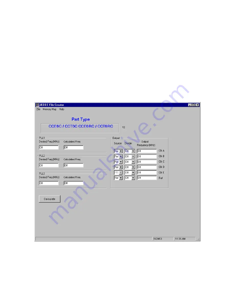
Page 7: ...Please select the type of part to be programmed and package type Select OK when ready The main screen should now be visible...
Page 8: ...eed output frequencies of 155 52 MHz 38 88 MHz 53 125 MHz and 106 25 MHz Since 155 52 MHz can be divided by 4 to get 38 88 MHz and 106 25 can be divided by 2 to get 53 125 we will be using 155 52 and...
Page 9: ...The OK in the Calculated Freq box indicates that the program has found acceptable values for the PLL frequency and we can proceed to the next step...
Page 10: ...sed as a source instead of a PLL frequency The Ref frequency is determined at startup when the part was selected If you look at the Main Screen you will see a number next to the Part Type This is the...
Page 11: ...dropdown box and select 4 Click the Calculate button You have just setup Clk B for 38 88 MHz Lets setup Clk C and Clk D Click source C dropdown box and select PLL2 Click Divider C dropdown box and sel...
Page 12: ...You are now ready to create the JEDEC file...
Page 13: ...1 3 Saving the file to disc If all looks good it is time to save the file to disc From the File dropdown box select Save As Enter a file name and click on the Save Button The JEDEC file is now create...
Page 14: ...ors from Cardinal Components The SCMF Test Board consists of the following basic components The 6 test SMA connectors which can be used for frequency measurement The I2 C connector which can be used b...
Page 15: ...by setting up the SCMF Test Board for frequency measurement only When using the SCMF Test Board as a stand alone unit 5 Volts DC must be applied to the board Attach a cable from the SCMF Test Board 5...
Page 16: ...700 adaptor socket if measuring a Multiple Output part insert the oscillator and adaptor into the ZIF socket Marked on the board at the SMA connectors are the Clock outputs There is also a Ref output...
Page 17: ...ration and EEPROM access The pin outs for this connection are shown if Figure 2 Please note If there is a 3 3 volt source available then the SClk SData Gnd and VI2 C 3 3 volts can all be connected to...
Page 18: ...2 3 Reconfiguring an Oscillator Using the hex file created by the Jedec Creator program the memory address and data information can be programmed into the oscillator See Figure 3 for a typical hex fil...
Page 19: ...ial Electrically Erasable PROM Writing and Reading to the EEPROM is done in the same way as Writing to the oscillator The address of the EEPROM is ACh default but can be changed by jumpers JP5 JP7 See...
Page 20: ...Cardinal Components Inc 155 Rt 46 West Wayne N J 07470 973 785 1333 www cardinalxtal com SCMFdocrev2...