Cardin Elettronica 105/SLi824 Instruction Manual Download Page 19

19

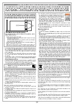
CONNECTING THE ANTENNA 

Connect an 

ANS400

 tuned antenna using a coaxial cable 

RG58

 (impedance 

50

Ω) 

with a maximum length of 

15 m

.

1) Automatic

Selected by enabling automatic reclosing (Automatic reclosing "

ON

" on the display). 

When the door is completely closed the opening command will start a complete cycle 

which will end with automatic reclosing. 
Automatic reclosing starts after the programmed pause period has elapsed (minimum 

2 seconds) when the opening cycle has been completed or straight away after the 

intervention of a photoelectric cell (the intervention of a photoelectric cell causes the 

pause time to be reset). 
During the pause time "

Pause

" will flash on the display along with the remaining 

pause time.
pressing the blocking button during this period will stop automatic reclosing and 

consequently stop the display from flashing. The indicator light remains lit until the 

closing manoeuvre has terminated.

2) Semiautomatic

Selected by deactivating automatic reclosing (Automatic reclosing "

OFF

" on the 

display). Work cycle control using separate opening and closing commands. 
When the door has reached the completely open position the system will wait until it 

receives a closing command either via an external control button or via radio control, 

before completing the cycle. 
The indicator light remains lit until the closing manoeuvre has terminated.

3)  Manual manoeuvring with released motors

Releasing the motor the gate can be moved by hand; once the motor has been re-

engaged the programmer will recover the position after two consecutive attempts 

to arrive at the travel limit.

4) Emergency manoeuvre

By default the emergency manoeuvre is disabled, to enable it move the jumper to 

the position 

J3

 "ENABLE" (fig. 2). If the electronic programmer no longer responds 

to commands due to a malfunction you may use the 

EMRG1

 or 

EMRG2

 inputs to 

move the gate leaf manually (fig. 2). The 

EMRG1

 or 

EMRG2

 inputs directly com-

mand the motor without passing through the logic control.
Gate movement will be at normal speed and the direction depends on the installed 

position of the motor:
-  left-hand installed motor 

EMRG1

 closes and 

EMRG2 

opens;

-  right-hand installed motor 

EMRG1

 opens and 

EMRG2 

closes.

Attention!

 During the emergency manoeuvre all safety devices are 

disabled and there is no gate positioning control: release the commands 

before you are at the mechanical travel buffer. Only use the emergency 

manoeuvre in cases of extreme necessity.

After you have carried out an emergency manoeuvre the electronic programmer will 

lose the position of the gate ("out of pos" on the display) and therefore when normal 

operation is restored it will carry out a repositioning manoeuvre.
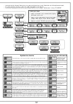
  If the "open-close" mode is set for the "

TD

" button (menu "OPTION") activating 

the "

TAL

" button will start the limited opening stage (only from the completely 

closed position) but while the gate is opening pressing the button again will 

have no effect. Once the opening position has been reached pressing the "

TAL

button will start closing after which pressing "

TAL

" again will have no effect.

  If the "open-block-close" mode is set for the "

TD

" button (menu "OPTION") 

activating the "

TAL

" button will start the limited opening stage (only from the 

completely closed position) pressing the button again will block the gate; press-

ing the button a third time will start the closing cycle. Pressing the "

TAL

" button 

again will have no effect.

•  If an opening command is received during limited opening; the limited opening 

command will become a full opening command. 

  If the 

FI

 photocell cuts in during the closing stage you will only have partial 

movement in the opening direction (It reopens only for the distance it has been 

closing the gate).

• 

Note:

 The limited opening command can also be given using the second channel 

radio function.

  The limited opening distance is set to half of the entire opening distance.

This device allows the propulsion unit to work during blackouts.
•   The programmer has a built in charger for an 

NiMH 24V

 battery that is managed 

by a dedicated micro controller. The control chip adjusts the voltage according to 

the condition of the connected battery. 

To avoid the risk of overheating only use the battery supplied by the 

manufacturer 

SPN 999540

.

If the battery shows signs of damage it must be replaced immediately.

The battery must only be installed/removed by qualified personnel. Used 

batteries must not be thrown into domestic rubbish bins and they must 

be disposed of according to the local standards and regulations in force.

•  The unit returns to normal operation once the power supply brought back on line.  

To use the battery again it must first be allowed to recharge. 

  The battery charge time with a battery in good condition can take up to a maxi-

mum of 

16 hours

. If the time required is greater you should consider replacing 

the battery. You are however advised to replace the battery every three years.

•  When the door has stopped, the controlled external devices (

CTRL 24 Vdc

) do not 

receive power in order to increase the autonomy of the battery. When a command 

is received however (

via radio

 or 

via cable

) the programmer sends power to the 

controlled external devices and checks their security status. It follows therefore 

that the command will be carried out (security devices at rest) with a one second 

delay to give time to restore the correct operation of the devices. If after this period 

a security device is found to be in alarm the command will not be carried out, power 

to the external devices will be cut off and the programmer will return to stand-by.
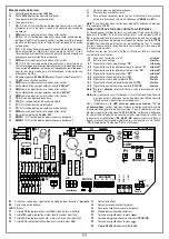
Note!

 If you wish to use an external receiver it must be wired to the binding posts 

16-17 (fig. 3) otherwise a command sent 

via radio

 will not be able to activate the door.

•  The self-sufficiency of the system when it is running on battery power is depend-

ent on the ambient conditions and on the load connected at binding posts 16-17 

(power is always routed there during blackouts).

When the battery is completely flat (during blackouts) the programmer 

will lose the position of the door and therefore when power returns (after 

the first command given) you will have to carry out the repositioning 

procedure (see page 21). For this reason you should avoid leaving the 

electronic programmer without power

 for lengthy periods (more 

than two days).

•  It is not possible to enter the programming mode when running off battery 

power.

•  During blackouts the battery supplies power to both the logic and the motor 

control parts of the programmer. 

  For this reason during battery powered operation the voltage applied to the 

motor is inferior to the voltage supplied during normal operation and the motor 

will therefore work slower and will not decelerate when approaching the travel 

limits.

Slot-in battery charger

The LED 

L3

 indicates the function mode as follows:

 Off

:  missing batteries or the electronic programmer is running 

off battery power (during a blackout). During the first 10 

seconds of operation from the start up of the electronic 

programmer the battery charger is blocked. After this period 

has elapsed it may either start self-diagnostics  (indicated 

by a lengthy flashing of the Led) or it will start recharging 

(Led continuously lit);


Brief flashing: 

voltage variation has been detected at the battery charger 

binding posts (e.g. when the batteries are being connected 

or removed);


Single flashing: 

this repeats every 2 seconds indicating that the batteries 

are being topped up to maintain their level;


Remains lit: 

the batteries are charging. The charge time depends on a 

number of factors and can last up to 16 hours. Using the 

motor will increase the time needed for charging.

Battery check

With the gate in the completely closed position and the display switched off. Check 

that LED "

L3

" (battery charging) is giving off 

"one flash at a time"

.

Switch off the power at the mains and make sure that the display indicates that it is 

working off battery power and that the charge is greater than 90%. Give a movement 

command and measure the overall voltage


: The reading should be at least 

22 Vdc

.

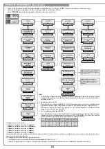
LIMITED OPENING (PEDESTRIAN ACCESS)

BATTERY POWERED OPERATION

FUNCTION MODES

CS1256B

DC0450

L3

Scheda di innesto

 PRG424BC

08-01-2008

DC0435

Description :

Product Code :

Date :

Drawing number :

P.J.Heath

CARDIN ELETTRONICA S.p.A

  - 31020 San Vendemiano (TV) Italy - via Raffaello, 36 Tel: 0438/401818 Fax: 0438/401831

Draft : 

All rights reserved. Unauthorised copying or use of the information contained in this document is punishable by law 

Scheda carica batteria

Summary of Contents for 105/SLi824

Page 1: ...ATTENZIONE Prima di iniziare l installazione leggere le istruzioni attentamente Verifiche preliminari Impianto tipo Pagine 3 4 Schema elettrico impianto tipo Pagina 5 Avvertenze importanti Pagina 6 Istruzioni per l installazione Pagine 7 8 Sblocco manuale Pagina 8 Collegamento elettrico Pagine 8 9 Procedura di programmazione Pagina 10 12 Riposizionamento automatico Pagina 12 Comando via radio Pagi...

Page 2: ... x x x x x x x x x x x x x x x x x x x x x x x x x x x x x x x x x x x x x x x x x x x x x x x x x x x x x x x x x x x x CARDIN ELETTRONICA spa Via del lavoro 73 Z I Cimavilla 31013 Codognè TV Italy Tel 39 04 38 40 40 11 Fax 39 04 38 40 18 31 e mail Italy sales office it cardin it e mail Europe sales office cardin it http www cardin it Il costruttore CARDIN ELETTRONICA S p A DICHIARA CHE L APPAREC...

Page 3: ...rmoire électronique 5 Clignoteur 6 Antenne 7 Bord de sécurité Attention le schéma diffusé à titre purement indicatif est destiné à vous aider dans le choix des composants électroniques Cardin à utiliser Par conséquent il n a aucune valeur obligatoire quant à la réalisation de l installation ZEICHENERKLÄRUNG 1 Getriebemotor 2 Interne Lichtschranke 3 Externe Lichtschranke 4 Elektronische Steuereinhe...

Page 4: ...OTOR SCHEMA ELETTRICO IMPIANTO TIPO STANDARD WIRING DIAGRAM SCHÉMA ÉLECTRIQUE DE L EXEMPLE D INSTALLATION ELEKTRISCHER SCHALTPLAN ANLAGENART ESQUEMA ELÉCTRICO INSTALACIÓN ESTÁNDAR 3 LEGENDA ANS400 Antenna esterna LS Lampada spia LP Lampeggiatore FTC RX Fotocellula ricevitore FTC TX Fotocellula trasmettitore TD Tasto dinamico SEL Selettore a chiave TB Tasto di blocco CP Costa sensibile LEGEND ANS40...

Page 5: ...e chiamare l assistenza tecnica Verificare periodicamente il funzionamento delle sicurezze fotocellule ecc Le even tuali riparazioni devono essere eseguite da personale specializzato usando materiali originali e certificati L uso dell automazione non è idoneo all azionamento in continuo bensì deve essere regolato in base ai vari modelli vedi caratteristiche pag 44 APERTURA AUTOMATICA NON AVVICINAR...

Page 6: ...a centralina di comando e la rete deve essere interposto un inter ruttore onnipolare con distanza di apertura tra i contatti di almeno 3 mm Nonutilizzarecavoconconduttoriinalluminio nonstagnarel estremità deicavidainserireinmorsettiera utilizzarecavoconmarcaturaTmin85 C resistente agli agenti atmosferici I conduttori dovranno essere adeguatamente fissati in prossimità della morsettiera in modo che...

Page 7: ...tralaricezionedelcomando e il moto del cancello passa circa 1 secondo Alimentare il circuito e verificare che lo stato dei LED e delle segnalazioni sul display sia come segue L1 Alimentazione scheda acceso L2 Errata connessione batteria spento 3 S1 Segnalazione tasto blocco TB acceso 4 S2 Segnalazione fotocellule d inversione FI acceso 4 S3 Segnalazione fotocellule di stop FS acceso 4 S4 Segnalazi...

Page 8: ...la centralina sono impostabili tramite menu sul Display LCD1 con i tre tasti posti sotto ad esso utilizzare le freccie per navigare all interno dei menù e o per la regolazione del contrasto del display utilizzare PROG OK per modificare l impostazione del parametro scelto e o per dare conferma Note 1 La lampada spia lampeggia lentamente durante l apertura velocemente durante la chiusura resta acces...

Page 9: ...de il moto nella direzione in cui era stato interrotto dopo aver effettuato un prelampeggio di 10 secondi Quando interviene il sensore l anta inverte immediatamente il moto per qualche istante sia in chiusura che in apertura in modo da liberare l ostacolo poi rimane ferma per 3 minuti e trascorso questo lasso di tempo riprende il moto nella direzione in cui era stato interrotto dopo aver effettuat...

Page 10: ...ezzo secondo dopodiché il ricevitore sarà pronto a memorizzare un altro codice 4 Per uscire dalla modalità lasciare trascorrere 3 sec senza memorizzare codici Il ricevitore emetterà un bip della durata di 5 sec ed uscirà dalla modalità Nota Quando la memoria viene completamente occupata il buzzer emetterà 10 bip ravvicinati uscendo automaticamente dalla modalità di memorizzazione via radio la stes...

Page 11: ...ermette il funzionamento del sistema anche in assenza di rete Il programmatore dispone di un circuito di carica per batteria NiMH a 24V gestito da un microcontrollore dedicato che regola la tensione in relazione allo stato della batteria innestato tramite connettore Per evitare il rischio di surriscaldamento utilizzare soltanto batterie fornite dal costruttore codice ricambio 999540 Se la batteria...

Page 12: ...12 NOTES ...

Page 13: ... to 70 C In case of failure or operational anomalies switch off the power at the mains do not attempt to repair the appliance yourself Periodically check the correct operation of all safety devices photoelectric cells etc Eventual repair work must be carried out by specialised personnel using original spare parts Theapplianceisnotsuitableforcontinuousoperationandmustbeadjustedaccording to the mode...

Page 14: ...E DRIVE SHAFT MANUAL RELEASE MECHANISM INSTRUCTIONS FOR USE IMPORTANT REMARKS ELECTRONIC PROGRAMMER This device has been created to be integrated into the structure of specially made sliding gates The geared motor is fitted with screw type attachments that allow it to be fitted inside metal profiles ASSEMBLY PROCEDURE The unit may be positioned either to the right or to the left of the passageway ...

Page 15: ... the security devices must be connected to the binding post marked CTRL 30 Vdc If the test is active there will be a 1 second delay between the command transmission and movement of the gate Switch on the power and make sure that the indicator LEDs are indicating the following conditions L1 Power on ON L2 Wrong battery connection OFF 3 S1 Indicator for the blocking button TB ON 4 S2 Indicator for t...

Page 16: ...LS 1 6 PROGRAM T B F S F I CP 00 000 001 T B F S F I CP PROG OK to set PAUSE TIME 30 OK FW_0 11 5 Current sensor settings Level 1 motor electrical input 2 amps Level 2 motor electrical input 2 5 amps Level 3 motor electrical input 3 amps Level 4 motor electrical input 4 amps Level 5 motor electrical input 5 amps The programmer checks the electrical input to the motor detecting any eventual increas...

Page 17: ...ror occurs during normal motor operation it means that there is a problem with one of the encoder signals Check the relative connections and carry out automatic repositioning The gate movement direction is different from the encoder setting eg the gate moves in the closing direction while the program is carrying out the opening stage Check the motor power supply connections Current sensor error Wh...

Page 18: ...nother code 4 To leave the programming mode wait for 3 seconds without pressing any buttons The receiver will sound a five second long beep and will then exit the program ming mode Note When the memory is entirely occupied the buzzer will sound 10 rapid beeps and will automatically leave the programming via radio mode The same signal is given each time you try to enter programming via radio when t...

Page 19: ...ontroller The control chip adjusts the voltage according to the condition of the connected battery To avoid the risk of overheating only use the battery supplied by the manufacturer SPN 999540 If the battery shows signs of damage it must be replaced immediately The battery must only be installed removed by qualified personnel Used batteries must not be thrown into domestic rubbish bins and they mu...

Page 20: ...20 NOTES ...

Page 21: ... immédiatement hors tension et contacter le service d assistance technique Contrôler régulièrement le fonctionnement des dispositifs de sécurité cellules photoélec triques etc Les éventuelles réparations devront être effectuées par un personnel spécialisé qui devra prendre soin de monter exclusivement des pièces détachées d origine et certifiées L automatismen estpasadaptéàuneactivationcontinue l ...

Page 22: ...stanza di apertura tra i contatti di almeno 3 mm Nonutilizzarecavoconconduttoriinalluminio nonstagnarel estremità deicavidainserireinmorsettiera utilizzarecavoconmarcaturaTmin85 C resistente agli agenti atmosferici I conduttori dovranno essere adeguatamente fissati in prossimità della morsettiera in modo che tale fissaggio serri sia l isolamento che il condut tore COLLEGAMENTO ALIMENTAZIONE 230 Va...

Page 23: ...r toutes les entrées et les sorties 9 FS N F 8 2 kΩ entrée pour dispositifs de sécurité cellule photoé lectrique d arrêt Une fois que la cellule n est plus occultée le portail repartira en fermeture après le temps d arrêt uniquement en mode automatique 10 FI N F 8 2 kΩ entrée pour dispositifs de sécurité cellule photoélec trique d inversion en fermeture L ouverture de ce contact suite à l interven...

Page 24: ...MÈTRES OK PROG OK pour programmer DIST BUTÉE FERM 6 étape 0 9 TOUCHE DYNAMIQUE OUVRE FERME OUVRE STOP FE PROG OK pour programmer REF AUTOMATIQUE ON OFF PROG OK pour programmer PROG OK pour programmer CLIGNOTEUR FIXE CLIGNOTANT PROG OK pour programmer LAMPE TÉMOIN 1 FIXE CLIGNOTANT PROG OK pour programmer MODALITE FI 2 EN FERMETURE AUSSI EN STOP PROG OK pour programmer PROG OK pour programmer PROG ...

Page 25: ...eci se produit pendant l utilisation normale du moteur il y a un problème sur les signaux inhérents à l encodeur vérifier les relatives connexions et lancer le repositionnement automatique Erreur de direction de l encodeur Le sens de marche du portail est différent de celui établi par l encodeur par exemple le portail va en fermeture alors que le programmateur réalise la phase d ouverture Contrôle...

Page 26: ...on a eu lieu en émettant 2 bips d une demi seconde Après quoi le récepteur sera prêt à mémoriser un autre code 4 Pourquitterleprocédédemémorisation laisserpasser3secondessansmémoriser decodes L avertisseursonoreémettraunbipde5secondesetsortiraduprocédé Note lorsque la mémoire est pleine l avertisseur sonore émet 10 bips très courts et on sort automatiquement du procédé de mémorisation via radio Ce...

Page 27: ... Ouverture partielle Le dispositif permet le fonctionnement du groupe opérateur même en cas de coupure de courant Leprogrammateurdisposed uncircuitdechargepourbatteriesNiMHà24V enfiché sur connecteur et géré par microcontrôleur dédié qui régule la tension en fonction du niveau de charge de la batterie Pour parer au risque de surchauffe utiliser exclusivement des batteries fournies par la fabricant...

Page 28: ...28 NOTES ...

Page 29: ...reich von 20 C bis 70 C geeignet sind Im Falle von Störungen oder Unregelmäßigkeiten beim Betrieb ist die Stromversorgung vor dem Einlass in die Apparatur zu unterbrechen und der technische Kundendienst zu rufen Die Funktionstüchtigkeit der Sicherheitsvorrichtungen Lichtschranken usw ist periodisch zukontrollieren EventuelleReparaturensindvonFachpersonalundunterVerwendungvon zertifizierten Origina...

Page 30: ...ischenderSteuereinheitunddemStromversorgungsnetzmussein allpoliger Schalter mit einem Kontaktenabstand von mindestens 3 mm zwischengeschaltet werden Keine Leitungen mit Aluminiumleiter verwenden in die Klemmleiste einzuführende Kabelenden nicht verzinnen Kabel mit der Markierung T min 85 C wetterbeständig verwenden Die Leitungen müssen in der Nähe der Klemmleiste in angemessener Weise so befestigt...

Page 31: ...er CTRL 30 Vdc angeschlossen werden Es ist zu beachten dass bei eingeschaltetem Test zirka 1 Sekunde zwischen dem Befehlseingang und der Inbewegungssetzung des Schiebertors vergeht Den Schaltkreis mit Strom versorgen und prüfen ob der Zustand der Anzeige LED wie nachstehend bezeichnet ist L1 Leiterplatten Stromversorgung leuchtet L2 falsche Batterieanschluss erloschen 3 S1 Anzeige für Blockiertast...

Page 32: ... SEK DREHMOMENT WAHL 4 NIVEAU 1 6 PROGRAM T B F S F I CP 00 000 001 T B F S F I CP PROG OK zum Einstellen ABST ÖFFN ANSCHL 6 0 9 SCHRITTE FW_0 11 Alle Funktionen des Steuergeräts können über das Menü im Display LCD1 mit den drei darunterliegenden Tasten eingestellt werden Für das Navigieren im Menü und oder die Einstellung des Kontrasts im Display die Pfeile benutzen PROG OK für die Änderung der E...

Page 33: ...Steuereinheit liegen Wenn dies bei der normalen Verwendung des Motors auftritt bedeutet dies dass ein Problem mit der Encoder Signalen besteht Die Anschlüsse überprüfen und die automatische Rückstellung ausführen Die Laufrichtung des Torflügels ist anders als wie vom Encoder festgelegt z B Das Schiebetor schließt während die Steuerung die Öffnung ausführt Den Anschluss der Motoren Stromversorgung ...

Page 34: ...hne einen Code zu speichern ver streichen lassen Der Empfänger gibt einen 5 Sekunden dauernden Bip Ton von sich und verlässt den Speichermodus Anmerkung Wenn der Speicher voll ist gibt der Summer zehn schnell aufeinan derfolgende Bip Töne von sich und beendet automatisch den funkgesteuerten Speichermodus Das Gleiche geschieht auch bei jedem Versuch sich bei vollem Speicher in den funkgesteuerten S...

Page 35: ... Netzversor gung Die Steuerung verfügt über einen Ladekreis für NiMH Batterien auf 24V der gesteuertwirdvoneinemeigenenMikrocontroller derdieSpannungabhängigvom Zustand der Batterie regelt Der Ladekreis wird über einen Stecker eingeschaltet Um das Risiko der Überhitzung zu vermeiden sind nur vom Hersteller gelieferteBatterienzubenutzen Ersatzteil Nr 999540 WenndieBatterie Zeichen von Beschädigunge...

Page 36: ...36 NOTES ...

Page 37: ...esconectar la alimentación eléctrica antes del equipo y contactar con el servicio de asistencia técnica Comprobar periódicamente el funcionamiento de los dispositivos de seguridad fotocélulas etc Las reparaciones eventuales deben ser realizadas por personal cualificado utilizando materiales originales y certificados El uso de la automatización no es idóneo para el accionamiento continuo sino que s...

Page 38: ... debe encargarse de sustituir el cable de alimentación Entre la centralita de control y la red se deberá intercalar un interruptor omnipolar con distancia de apertura entre contactos de 3 mm como mínimo No utilizar cables con conductores de aluminio no estañar el extremo de los cables que deben introducirse en la placa de bornes utilizar un cable con marcado T mín 85 C resistente a los agentes atm...

Page 39: ...mente un segundo tras la recepción de un control y el movimiento de la cancilla Alimentar el circuito y comprobar que el estado de los LEDs y de las señalizaciónes en el display resulte tal como se indica a continuación L1 Alimentación tarjeta encendido L2 Conexión batería errónea apagado 3 S1 Señalización tecla de bloqueo TB encendido 4 S2 Señalización fotocélulas de inversión FI encendido 4 S3 S...

Page 40: ...rados en fábrica excluido el número de maniobras Pulsar EXIT para salir sin modificar los parámetros FW_0 11 Todas las funciones de la centralita pueden configurarse mediante el menú en el Display LCD1 con las tres teclas situadas debajo del mismo utilizar las flechas para navegar en los menús y o para regular el contraste del display utilizar PROG OK para modificar la configuración del parámetro ...

Page 41: ...que existe un problema en las señales correspondientes al encoder comprobar los conexionados correspondientes y realizar el reposicionamiento automático El sentido de marcha de la cancilla es diferente del establecido por el encoder ejemplo la cancilla se cierra mientras el programador está realizando la fase de apertura Controlar el conexionado de la alimentación del motor Error del sensor de cor...

Page 42: ... de medio segundo y a continuación el receptor estará listo para memorizar otro código 4 Parasalirdelamodalidad esperar3segundossinmemorizarcódigos Elreceptor emitirá un bip de 5 segundos de duración y saldrá de la modalidad Nota cuando la memoria ha sido ocupada por completo el avisador acústico emitirá 10 bips uno tras otro saliendo automáticamente de la modalidad de memorización vía radio La mi...

Page 43: ...matambiéncuandofaltalacorriente El programador dispone de un circuito de carga para batería NiMH a 24V diri gido por un microcontrolador dedicado que regula la tensión en relación con el estado de la batería acoplado por medio de conector Para evitar el riesgo de recalentamiento utilizar únicamente las baterías suministradas por el fabricante código de repuesto 999540 Sustituir la batería cuando m...

Page 44: ... 44 Température de fonctionnement C 20 55 Caractéristiques du programmateur Alimentation Vac 230 Intensité absorbée A 1 2 Puissance absorbée maxi W 250 Indice de protection IP 55 Appareil de classe II Cls Récepteur incorporé Fréquence de réception MHz 433 92 Nombre de canaux Nbre 4 Nombre de fonctions disponibles Nbre 2 Nombre de codes mémorisables Nbre 300 Technische Daten des Antriebs Motorstrom...

Reviews: