


MTF 9/15
C
ONTROLLER
O
PERATION
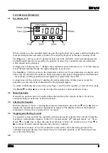
4.1 Eurotherm 2132
When switched on, the controller lights up, goes through a short test routine, and then displays the
measured temperature and starts to control. The output light glows or flashes as heating occurs.
The
Page
key
allows access to parameter lists within the controller; most lists and parameters
are hidden and cannot be accessed by the operator because they contain factory-set parameters
which should not be changed.
A single press of the page key
displays the temperature units, normally set to °C; further presses
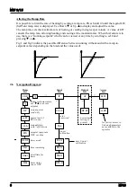
reveal the lists indicated in the Navigation Diagram in section 4.6.
The
Scroll
key
4
allows access to the parameters within a list. Some parameters are display-only;
others may be altered by the operator. Some parameters only appear in appropriate circumstances
– for example, working setpoint does not appear if setpoint ramp rate is Off.
A single press of the scroll key
4
displays the temperature units; further presses reveal the
parameters in the current list indicated in the Navigation Diagram.
To return to the Home list at any time, press Page
and Scroll
4
together, or wait for 45 seconds.
The
Down
T
and
Up
S
keys are used to alter the setpoint or other parameter values.
4.2 Basic Operation
Normally no operator action is required other than entering the setpoint, as the 2132 starts to
control on being switched on, as described above.
4.3 Altering the Setpoint
With the display at “home”, showing the measured temperature, press Down
T
or Up
S
once to
display the setpoint; press again or hold down to adjust it. The display returns to the measured
temperature when no key is pressed for 0.5 seconds.
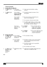
4.4 Stopping and Starting Control
It is possible to stop and start the controller without altering the setpoint. Press Scroll
4
until the
legend
m-A
(manual/auto) appears. In the 2132, manual means “off” and auto means “on”. Press
Down
T
or Up
S
once to show the current on/off state:
mAn
for off, and
Auto
for on. Press
T
or
S
to change between manual and auto (off and on) as required.
Note that timer modes 1 & 3 set the controller to
mAn
at the end of the timing period. If the
controller unexpectedly does not control it may be in manual, possibly as the result of previous
use of the timer function.
4.5
MF09
5