background image


HRF 


MF05 

F

AULT 

A

NALYSIS


A.


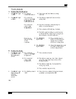
Furnace Does Not Heat Up


1. 

The 

HEAT

 light 

 is 

ON


Æ

  The heating 

element has failed 

Æ

Check also that the SSR is working 
correctly 
 

2. 

The 

HEAT

 light  

is 

OFF


 The 

controller 

shows 

a very high 

temperature

 or a 

code such as S.br 
 

Æ

The thermocouple has broken or has a 
wiring fault 


 The 

controller 

shows a

 low 

temperature


Æ

The door switch(es) (if fitted) may be 
faulty or need adjustment 


Æ

The contactor (if fitted) may be faulty 


Æ

The SSR could be failing to switch on due 
to internal failure, faulty logic wiring from 
the controller, or faulty controller 


There are no 
lights glowing 
on the 
controller 

Æ

The 

SUPPLY


light is 

ON


Æ

The controller may be 
faulty or not receiving a 
supply due to a faulty 
switch or a wiring fault 


Æ

The 

SUPPLY


light is 

OFF


Æ

Check the supply fuses and 
any fuses in the furnace 
control compartment 
 

B.


Furnace Overheats


1. 

The 

HEAT

 light 

goes 

OFF

 with 

the instrument 
switch 

Æ

  The controller 

shows a 

very high 

temperature 

Æ

The controller is faulty 


Æ

  The controller 

shows a 

low 

temperature 

Æ

The thermocouple may have been shorted 
out or may have been moved out of the 
heating chamber 


Æ

The thermocouple may be mounted the 
wrong way round 


Æ

The controller may be faulty 
 

2. 

The 

HEAT

 light 

does not go off


with the 
instrument 
switch 

Æ

  The SSR has failed 

“ON” 

Æ

Check for an accidental wiring fault which 
could have overloaded the SSR 


7.0 


Summary of Contents for HRF 7/22

Page 1: ...to the electricity supply CONTENTS Section page 1 0 Symbols Warnings 1 2 0 Installation 3 3 0 Operation 5 4 0 Maintenance 6 5 0 Repairs Replacements 7 6 0 Fault Analysis 9 7 0 Circuit Diagrams 10 8 0...

Page 2: ...glows Heat Light the adjacent light glows or flashes to indicate that power is being supplied to the elements 1 2 Warning Symbols DANGER of electrical shock read any warning printed by this symbol DA...

Page 3: ...re that there is free space around the furnace Do not obstruct any of the vents in the control section they are needed to keep the controls cool Ensure that the furnace is placed in such a way that it...

Page 4: ...ses customer fusing is preferred but not essential Furnace with supply cable either wire directly to an isolator or fitted with a line plug Furnace without supply cable a permanent connection to a fus...

Page 5: ...ating elements are isolated Find and correct the cause before resetting the overtemperature controller according the instructions supplied To switch the furnace off set the Instrument switch to O If t...

Page 6: ...by mail order A telephone call or fax often enables a fault to be diagnosed and the necessary spare part despatched Each furnace has its own record card at Carbolite In all correspondence please quote...

Page 7: ...mend reference to the European Ceramic Fibre Industry Association Bulletin No 11 and the UK Health and Safety Executive Guidance Note EH46 We can provide further information on request Alternatively o...

Page 8: ...ng to the new element Remove the chimney open the furnace door and slide out the chamber liner Withdraw the element through the front of the furnace Insert the new element through the glands and refit...

Page 9: ...no lights glowing on the controller The SUPPLY light is ON The controller may be faulty or not receiving a supply due to a faulty switch or a wiring fault The SUPPLY light is OFF Check the supply fuse...

Page 10: ...ply light Instrument Switch E coil temperature controller thermocouple overtemp controller thermocouple L N F1 F2 Filter if fitted contactor R BU Fan Motor Capacitor BR BU Fan Motor Capacitor BR BU he...

Page 11: ...fuses Required if no supply cable fitted Recommended if cable fitted See rating label for amperage see table below for fuse rating Model phases Volts Supply Fuse Rating HRF 7 22 1 phase 220 240 15A or...

Page 12: ...g the details below UK Office Keison Products P O Box 2124 Chelmsford Essex CM1 3UP England Tel 44 0 330 088 0560 Fax 44 0 1245 808399 Email sales keison co uk Please note Product designs and specific...

Reviews: