background image


Version 31.01.2013


USB-E65-TV


Pa

ge


1.2.


Check compatibility of vehicle and accessories 


1.3.


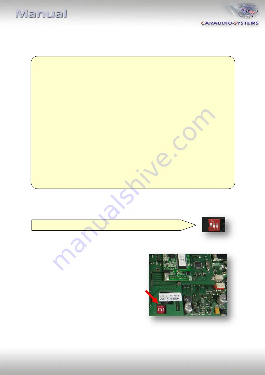
Setting the dip switches of the CAN-box TV-436 


1.4.


Setting the dip switches of the USB-box USBC-M536 


The default dip switch settings of the USB-box  
need to be changed ONLY if a rear-view camera is  
or shall be connected or if the AV-input of the  
usbLOGiC shall be deactivated. The dip switches are 
 located 

inside

 the USB-box. For changes it is  

necessary to open the box. Default settings are: 
  
dip1 = ON, dip2 = OFF, dip3 = ON 


Requirements 


Vehicle


7series (E65/E66) 


Navigation


Navigation system 

Professional

 E65 (older 1/2-button iDrive 

or CIC (newer 8-button iDrive) with 8.8” monitor 


Limitations 


factory-TV-tuner


Must NOT be installed. If uninstalled, optical ring must be closed. 


factory DVD-changer   

After-market rear-view camera cannot be connected to 

or factory nightvision   

the usbLOGiC interface. 


factory   


Additional interface VL-RGB02-R is necessary 

rear-seat-entertainment 


After-market rear-view cam  

Only works from usbLOGiC mode, not from OEM.  


USB-port 


Only for media which work with power supply by ONE single USB 


connector 


Factory PDC 

If an after-market rear-view camera should be connected by the 
usbLOGiC the visual PDC display must be deactivated 
occasionally or permanently for camera picture. 


All vehicles 


dip 1 ON, dip 2 OFF, dip 3 OFF 


Summary of Contents for usbLOGiC USB-E65-TV

Page 1: ...3 AVI VOB MOV RMVB JPG and many more last position memory integrated into and controllable by vehicle infotainment AV input with IR control channel control of after market devices by OEM buttons e g DVD player USB iPod devices after market rear view camera input automatic switching to rear view camera input only from usbLOGiC mode rear view camera power 12V max 1A rear seat entertainment AV output...

Page 2: ...IR remote control set 2 4 Connecting peripheral devices 2 4 1 AV source 2 4 2 Installing AV source s IR sensor additionally 2 4 3 After market rear view camera 2 4 4 After market rear seat entertainment 2 4 5 Factory nightvision factory DVD changer factory rear view camera 3 Operation 3 1 Activation of the video in motion function 3 2 Selecting the usbLOGiC as current AV source 3 3 Assigning devic...

Page 3: ...rfaces for one year after purchase To receive a free update the interface must be sent in at own cost Labor cost for and other expenses involved with the software updates will not be refunded 1 Prior to installation Read the manual prior to installation Technical knowledge is necessary for installation The place of installation must be free of moisture and away from heat sources 1 1 Delivery conte...

Page 4: ...igation system Professional E65 older 1 2 button iDrive or CIC newer 8 button iDrive with 8 8 monitor Limitations factory TV tuner Must NOT be installed If uninstalled optical ring must be closed factory DVD changer After market rear view camera cannot be connected to or factory nightvision the usbLOGiC interface factory Additional interface VL RGB02 R is necessary rear seat entertainment After ma...

Page 5: ...t In order to disable the AV input of the usbLOGiC set dip1 OFF down 2 Installation Switch off ignition and disconnect the vehicle s battery If according to factory rules disconnecting the battery has to be avoided it is usually sufficient to put the vehicle in sleep mode In case the sleep mode does not show success disconnect the battery with a resistor lead Complete and correct function of the i...

Page 6: ...creen Remove cover grill only plugged Place soft towel beneath the navigation monitor to avoid scratches Flip down the board monitor NOTE The OEM screen gets stuck with its connector at the upper side of the cockpit Insert a hard plastic sheet like a credit card to prevent cockpit from taking damage Remove the black connector at the backside of the screen as shown below ...

Page 7: ... Insert the completed black connector into CAN interface harness TV BMW65 Connect 12 pin insert from CAN interface harness TV BMW65 into black connector from vehicle harness Insert completed connector into the plug on the backside of the navigation monitor Connect 8pin Molex connector of TV BMW65 to CAN box TV 436 NOTE Pictures do NOT show the fibre optics connected in car ...

Page 8: ...alled Remove the factory optical leads of the factory TV tuner port blue female connector and connect it to the black male MOST connector enclosed to harness C2C BMW01 Pay attention to the directional arrow on the optical lead connectors Connect the black male MOST connector to the female MOST connector on the rear of the USB box USBC M536 OPTICAL Connect the blue male connector of harness C2C BMW...

Page 9: ...nternal USB functions additionally to the control through the navigations buttons Connect the C3C SENSOR to the female black red blue 3pin AMP connector of harness C3C AVIR and locate the sensor in an accessible place 2 4 Connecting peripheral devices It is possible to connect an after market AV source after market rear view camera and rear seat entertainment to the usbLOGiC Also factory nightvisi...

Page 10: ...A port AV1 of the USB box USBC M536 with the AV output of the AV source The pink ACC output wire 12V max 1A of harness C2C BMW02 can be connected to the ACC input wires of the connected device to switch it on It carries 12V when the navigation computer is running 2 4 2 Installing AV source s IR sensor additionally Additionally to the control via OEM navigation it is possible to install the origina...

Page 11: ...harness C2C BMW02 can be used as 12V power max 1A supply for the rear view camera Note Automatic switching to the camera input when reverse gear is engaged works only in usbLOGiC mode With an existing factory PDC the visual PDC display must be deactivated occasionally or permanently by iDrive while operating in the vehicle settings for camera picture If needed the PDC display can be switched on by...

Page 12: ...r seat entertainment monitors If not or if connecting more than two monitors use a video splitter 2 4 5 Factory nightvision factory DVD changer factory rear view camera On vehicles with factory nightvision factory DVD changer or factory rear view camera pin out the video signal and video signal ground from the white 18pin AMP connector of the vehicles harness rear of navigation computer and connec...

Page 13: ...tems AV and AV RCxx will not be available 3 4 Switching to internal USB AV source or after market rear view camera In the usbLOGiC control menu choose TV to enter internal USB mode AV to enter AV input mode not available if AV input is deactivated see chapter Deactivating usbLOGiC AV input or REAR CAM to switch to the usbLOGiC after market rear view camera input even if the automatic switching to ...

Page 14: ...H short UP UP Up Up Previous chapter WEST long MEDIA EXIT Play Resume Play Resume Play resume WEST short LEFT LEFT Left Left Left SOUTH long SOURCE Source Source Source SOUTH short DOWN DOWN Down Down Next chapter EAST long POWER AUTO Zoom Next DVD or DVD selection menu KCE increase vol Vlink ESC EAST short RIGHT RIGHT Right Right Right Left turn Previous Track Previous channel Previous chapter Pr...

Page 15: ...t 0 8A max Temperature range 30 C to 80 C Weight 312g Measurements box only B x H x T 135 x 30 x 105 mm 5 Connections USB box 6 Technical Support Caraudio Systems Vertriebs GmbH manufacturer distribution In den Fuchslöchern 3 D 67240 Bobenheim Roxheim email support caraudio systems de Legal disclaimer Mentioned company and trademarks as well as product names codes are registered trademarks of thei...

Reviews: