Car-Interface.com r.Link CI-UCON5N Manual Download Page 22


Version 22.10.2020 

HW CAM(V100)(V12) 

CI-UCON5N 

P

a

g

e

22


3.1.


Picture settings 


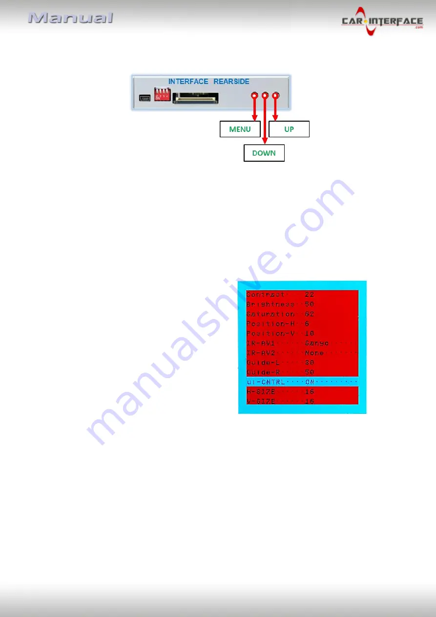
The picture settings can be adjusted by the 3 buttons on the video-interface. Press the 

MENU

 button to open the OSD settings menu. To switch to the next menu item, pressing 

UP


and 

DOWN

 will change the selected value. The buttons are embedded in the housing to 

avoid accidental changes during or after installation. The picture settings have to be done 
separately, AV1 and AV2 while the corresponding input is selected and visible on the 
monitor.  
 

Note: 

The OSD menu is only shown when a working video source is connected to the 

            selected video-input of the interface.


The following settings are available: 
 
Contrast 
Brightness 
Saturation 
Position H (horizontal) 
Position V (vertical) 
 For the rearIR-AV1 (out of function) 
IR-AV2 (out of function) 
Guide-lines left (out of function) 
Guide-lines right (out of function) 
Guide lines (ON/OFF) (out of function) 
 

Note:  

If the CAN-box does not support the vehicle’s CAN, the guide-lines cannot be used. 


4.


Specifications 

 
BATT/ACC range 


7V - 25V 

Stand-by power drain  


3,6mA 

Power   


112mA @12V  

Video input   


0.7V – 1V 

Video input formats   


PAL/NTSC 

RGB-video amplitude  


0.7V with 75 Ohm impedance 

Temperature range   


-40°C to +85°C 

Dimensions Video-Box 


115 x 25 x 89 mm (W x H x D) 


Summary of Contents for r.Link CI-UCON5N

Page 1: ...o sources Product features Video inserter for factory infotainment systems 1 CVBS Input for rear view camera 1 CVBS Input for front camera 2 CVBS video inputs for after market devices e g USB Player D...

Page 2: ...with daughter PCB 2 2 Connection schema 2 3 Connection to the head unit LVDS 2 3 1 Exception fot Chrysler vehicles 2 3 2 Warning notes concerning the installation of ribbon cables 2 4 Head unit frame...

Page 3: ...menu for DVD upgrades Changes updates of the vehicle s software can cause malfunctions of the interface Up to one year after purchase we offer free software updates for our interfaces To receive a fre...

Page 4: ...verse gear is engaged To delay the switch back an additional electronic part is required After market front camera The front camera will automatically be switched for 10 seconds after disengaging the...

Page 5: ...ches at the video interface Dip position down is ON and position up is OFF The front camera will automatically be switched for 10 seconds after disengaging the reverse gear See the following chapters...

Page 6: ...ly the required inputs disabled inputs will be skipped when switching through the video interfaces inputs 1 4 3 Rear view camera setting dip 5 If set to OFF the interface switches to factory picture w...

Page 7: ...use the vehicle s sleep mode In case the sleep mode doesn t succeed the battery has to be disconnected with a resistor lead The Interface needs a permanent power supply If power isn t directly taken f...

Page 8: ...Version 22 10 2020 HW CAM V100 V12 CI UCON5N Page 8 2 2 Connection schema...

Page 9: ...the head unit housing by 4 Torx screws T9 Clip out the head unit housing at the head unit control panel and fold it to the side like shown in the picture above Note The connected ribbon cables have t...

Page 10: ...the very short length of the ribbon cable there s only limited space for mounting available Connect the daughter PCB s pre assembeled 40pin ribbon cable to the previously become free ribbon cable bas...

Page 11: ...by using the 3 screws after the ribbon cable connection is done heed the following warning notes 2 3 2 Warning notes concerning the installation of ribbon cables 1 The contacting ends of ribbon cables...

Page 12: ...has to be cut away like shown in the following picture 2 5 Connection 20pin picture signal cable Connect the 20pin RGB digital cable s female 20pin connector to the male 20pin connector of the video i...

Page 13: ...tor to the male 10pin connector of the video interface Disconnect the female Quadlock connector of the vehicle harness from the rear of the head unit and connect it to the male Quadlock connector of t...

Page 14: ...oloured wire Manual ACC of the 12pin interface cable has to be connected additionately to 12V S contact terminal 86s e g glove compartment illumination Connect the female 12pin connector of the 12pin...

Page 15: ...be used to power an external source and has a different assignment depending on the position of dip switch 1 of the black 8 dips Dip Function Dip 1 ON 12V max 3A when reverse gear is engaged incl 10...

Page 16: ...in the production of the vehicle manufacturer there s always a possibility of incompatibility Connect the 12pin interface cable s female 12pin connector to the male 12pin connector of the video inter...

Page 17: ...is necessary to switch the audio signals 2 9 2 After market front camera The red power supply output ACC front cam out 12V max 3A can be used to power a front camera If Dip 1 is set to ON black 8 dips...

Page 18: ...Note Do not forget to set dip5 of the video interface to ON before testing 2 9 3 1 Case 1 Video interface receives the reverse gear signal If the CAN bus interface delivers 12V on the green wire of t...

Page 19: ...of the relay Disconnect the green cable s pre connected male and female connectors of the 12pin cable and connect the green input cable Reverse IN to the output connector 87 of the relay Note Not lea...

Page 20: ...rnal keypad Connect the keypad s female 4pin connector to the 12pin interface cable s male 4pin connector Note Even if the switching through several video sources by the keypad mightn t be required th...

Page 21: ...the next enabled input If all inputs are enabled the order is Factory video video IN1 video IN2 factory video By dip switch deactivated inputs will be skipped If an audio switch has been connected in...

Page 22: ...OSD menu is only shown when a working video source is connected to the selected video input of the interface The following settings are available Contrast Brightness Saturation Position H horizontal P...

Page 23: ...r order of LVDS cables is exactly connected according to manual Plugging into head unit does not work when the manual says to plug into monitor and vice versa Wrong monitor settings of video interface...

Page 24: ...ction RET or ALL is ON function for Asian market in the interface OSD Set interface OSD menu item UI CNTRL to ALLOFF or PDCON Not possible to switch video sources by OEM button CAN bus interface does...

Reviews: