background image

6-10KVA Rack-mount UPS User Manual                                     Introduction 


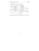
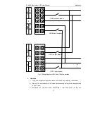
Fig 6. The Removable Power Distribution Box factory-attached


of long backup model 


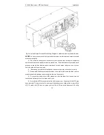
Fig 7. The Removable Power Distribution Box factory-attached of standard model


Summary of Contents for 10KL

Page 1: ...ed 220 230 240VAC 50 or 60Hz supply The factory default setting is 220VAC 50Hz Installation instructions and warning notices are in this manual The ups 06 10KVA 220 230 240VAC is designed for use with a three wire input L N G WARNING THE BATTERY CAN PRESENT A RISK OF ELECTRICAL SHOCK AND HIGH SHORT CIRCUIT CURRENT FOLLOWING PRECAUTIONS SHOULD BE OBSERVED BEFORE REPLACING THE BATTERY z Wear rubber ...

Page 2: ...Turn off and unplug the ups before cleaning it z Clean the UPS with a dry cloth Do not use liquid or aerosol cleaners z Never block or insert any objects into the ventilation holes or other openings of the UPS z Do not place the ups power cord where it might be damaged ...

Page 3: ...3 6 Battery 7 3 7 Dynamic Bypass 7 4 PRODUCT SPECIFICATION And PERFORMANCE 8 4 1 Model Description 8 4 2 Product Specification and Performance 8 5 INSTALLATION 10 5 1 Unpacking and Inspection 10 5 2 Rack mount Installation 10 5 2 Connect Input Output Power Cables 11 5 3 Operating procedure for connecting the long backup time model UPS with the external battery 15 5 4 Parallel operation 16 6 CONTRO...

Page 4: ...CEMENT PROCEDURES 26 9 1 Battery Disposal 26 9 2 External Battery Replacement Procedures 26 9 3 Internal Battery Pack Replacement Procedures 27 10 TROUBIE SHOOTING 28 10 1 Checking UPS status 28 10 2 Adjust the factors caused the problem 28 Annex A Intelligent Slot 33 Annex B EPO 34 ...

Page 5: ...d corrosive substance This UPS contains no user serviceable parts except the internal battery pack The UPS on off push buttons do not electrically isolate internal parts Under no circumstance attempt to gain access internally due to the risk of electric shock or burn Do not continue to use the UPS if the panel indications are not in accordance with these operating instructions or the UPS performan...

Page 6: ...ven damage equipment The series protects equipment from these disturbances The series is a compact rack mount on line UPS An on line UPS continuously conditions and regulates its output voltage whether utility power is present or not It supplies connected equipment with clean sine wave power Sensitive electronic equipment operates best from sine wave power For ease of use the series features a LCD...

Page 7: ...6 10KVA Rack mount UPS User Manual Introduction 3 Fig 2 Front View of standard Model Fig 3 Rear View of 6KVA Long Backup Model Fig 4 Rear View of 10KVA Long Backup Model ...

Page 8: ...t port SNMP card for network monitoring Intelligent card or non pluggable dry contact card for user extending Input circuit breaker Maintenance Bypass breaker External battery connector Parallel kit option Entries for hardwired power input and output cables intelligent slot for Dry contacts C13 Output receptacles C19 Output receptacles Output circuit breakers ...

Page 9: ...0KVA Rack mount UPS User Manual Introduction 5 Fig 6 The Removable Power Distribution Box factory attached of long backup model Fig 7 The Removable Power Distribution Box factory attached of standard model ...

Page 10: ...ensuring that the waveform of the input current used by the UPS is near ideal Extracting this sine wave input current achieves two objects z The utility power is used as efficiency as possible by the UPS z The amount of distortion reflected on the utility is reduced This results in cleaner power being available to other devices in the building not being protected by the ups 3 3 Inverter In normal ...

Page 11: ...lude value regulated non spoilable lead acid batteries outside To maintain battery design life operate the UPS in an ambient temperature of 15 25 C 3 7 Dynamic Bypass The ups provide an alternate path for utility power to the connected load in the unlikely event of a UPS malfunction Should the UPS have an overload over temperature or any other failure condition the ups automatically transfers the ...

Page 12: ...50 60 Input Voltage 176 275 VAC Current 34A max 57A max Battery Voltage 192VDC Current 37A max 60A max Output Voltage 220V 230V 240V Current 27 26 25A 45 43 42A Dimension W H D mm 438 130 680 438 218 680 438 130 680 438 218 680 Weight kg 18 5 62 21 5 70 5 2 Electrical Performance Input Model Voltage Frequency Power Factor 6KVA and 10KVA Single phase 40 70Hz 0 99 Full load Model No Type 6KS Standar...

Page 13: ...ude is above than 1000m the output power must be derated in use please refer to the following Altitude M 1000 1500 2000 2500 3000 3500 4000 4500 5000 Derating Power 100 95 91 86 82 78 74 70 67 1 0 9 lag 0 1 of normal THD 1 Full load Linear Load 110 load transfers to Bypass mode after 10 minutes 130 load transfers to Bypass mode after 1 min 150 load transfers to Bypass mode after 30 seconds and shu...

Page 14: ... the long backup model 2 Inspect the appearance of the UPS to see if there is any damage during transportation Do not turn on the unit and notify the carrier and dealer immediately if there is any damage or lacking of some parts 5 2 Rack mount Installation When using the ups in a rack mount configuration the UPS must be supported by a slide kit fixed rails or a shelf The adjustable rack mounting b...

Page 15: ... into the rack rails NOTE Reduce the risk of tipping the rack enclosure by placing the UPS or battery cabinet in the lowest possible rack position 5 2 Connect Input Output Power Cables 1 Notes for installation 1 The UPS must be installed in a location with good ventilation far away from water inflammable gas and corrosive agents 2 Ensure the air vents on the front and rear of the UPS are not block...

Page 16: ...ttached please refer to the appearance diagram 2 For 6KVA UPS it is recommended to select the UL1015 10AWG 6mm 2 wire or other insulated wire which complies with AWG Standard for the UPS input and output wirings 3 For 10KVA UPS it is recommended to select the UL1015 8AWG 10mm 2 wire or other insulated wire which complies with AWG Standard for the UPS input and output wirings NOTE Do not use the wa...

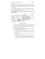
Page 17: ...6 10KVA Rack mount UPS User Manual Installation 13 Fig 8 Input and Output Terminal Block Wiring Diagram of distribution box for standard model ...

Page 18: ...green wire or green wire with yellow ribbon wire is used 6 After having completed the installation make sure the wiring connection is correct 7 Please install the output breaker between the output terminal and the load and the breaker should with leakage current protective function if necessary 8 To connect the load with the UPS please turn off all the loads first then perform the connection and f...

Page 19: ...ion 1 The nominal DC voltage of external battery pack is 192VDC Each battery pack consists of 16 pieces of 12V maintenance free batteries in series To achieve longer backup time it is possible to connect multi battery packs but the principle of same voltage same type should be strictly followed 2 The procedure of installing battery bank should be complied with strictly Otherwise you may encounter ...

Page 20: ...utput power sharing and power redundancy 2 Parallel installation 1 Users need to opt two standard 15 pin communication cables which length is appropriate to be less than 3m 2 Strictly follow the stand alone wiring requirement to perform the input wiring of each UPS 3 Connect the output wires of each UPS to an output breaker panel 4 Each UPS need an independent battery pack 5 Please refer to the wi...

Page 21: ...reaker Fig 11 Wiring Diagram of 6KVA and 10KVA in parallel 3 Operation 1 To perform the general operation follow the stand alone operating requirement 2 Startup The units transfer to INV mode simultaneously as they start up sequentially in Line mode 3 Shutdown the units shut down sequentially in INV mode When the last one ...

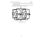
Page 22: ...s mode It is easy to operate the equipment with no previous training You just need to read through this manual and operate according to the instructions in it Rectifier PFC Inverter Bypass Charger UPS 1 Rectifier PFC Inverter Bypass Charger UPS 2 Utility Power Input Load Output 1 Output 2 Parallel Communication Cables Fig 12 Parallel Installation Diagram ...

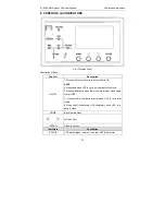
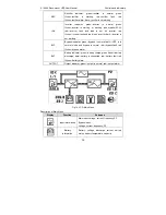
Page 23: ... NOTE Not available when UPS is set in automatically start mode 2 Press on off directly when there is no main input press again to start UPS 3 Press on off to shutdown inverter when UPS is in normal mode 4 Press on off to shutdown UPS completely when UPS is in battery mode HOME Back to main menu Left and right ENTER Press to choose Indicators Description STATUS UPS status green normal mode red UPS...

Page 24: ...rk inverter is not working BYP Bypass indicator green bypass is normal dark UPS is in normal mode and bypass is normal red bypass fault red flicker bypass alarm BAT Battery indicator green battery charge green flicker battery discharge dark battery is connected red battery fault red flicker battery alarm OUTPUT Output indicator green output is normal red output alarm Fig 14 LCD Main Menu Descripti...

Page 25: ... and function Set language contrast communication set SNT Modbus Modbus set Function function 1 transfer to bypass escape fault clear mute on off function 2 battery test maintenance test stop test History log Rated capacity 10KVA 1phase in out 1 1 Input voltage Battery voltage and capacity remained Output voltage and load percent System working mode S single mode E ECO mode P parallel mode 2 the u...

Page 26: ...ker of the battery pack is in the ON position this step only for long backup time model 2 Press the ON OFF button once to power on the LCD then press ON OFF button again choose YES to enter 3 A few seconds later the UPS turns into Battery mode 3 Turn off the UPS in normal mode 1 Press ON OFF button in condition of normal mode then choose YES to transfer to bypass 2 Open the input breaker to turn o...

Page 27: ... off its output immediately 2 Turn the input breaker off the external mains input breaker the output breaker and the battery breaker 3 Press the others UPSs s ON OFF button All of them transfer to the Bypass mode 4 Remove the parallel cables of the UPS that need to be removed 5 Press ON OFF button of remained UPSs then press YES to make the UPSs transfer to INV output 7 3 Maintenance Bypass Mainte...

Page 28: ...in the UPS after remove the power distribution box and battery connection cable please wait about 10 minutes in order that the BUS capacitor voltage in the internal automatically discharges 2 Place the UPS in inverter mode from maintenance bypass mode When finish maintenance of the UPS please use the following steps to switch the load supplying from maintenance bypass to inverter NOTE because it d...

Page 29: ...rged once every 4 to 6 months if it has not been used for a long time zIn the regions of hot climates the battery should be charged and discharged every 2 months The standard charging time should be at least 12 hours zUnder normal conditions the battery life lasts 3 to 5 years In case if the battery is found in bad condition earlier replacement should be made zBattery replacement should be perform...

Page 30: ...rcuit There may be hazardous voltage between the battery terminals and the ground 8 Even though the input breaker is disconnected the components inside the UPS are still connected with the batteries and there are potential hazardous voltages Therefore before any maintenance and repairs work is carried out switch off the breaker of the battery pack or disconnect the jumper wire of connecting betwee...

Page 31: ...tery access door from the UPS for reassembly 4 Gently disconnect the battery plugs and battery receptacles 5 Pull the internal battery packs out of the UPS 6 Line up and slide in the new replacement internal battery packs 7 Gently push the battery wire into the UPS battery compartment 8 Reconnect the battery plugs and battery receptacles 9 Reattach the front battery door with the six screws 10 Rea...

Page 32: ...op and contact your local representative or Channel Support z Check whether the battery is discharging When the utility input is normal the battery should not discharge If the UPS is operating in Battery Mode stop and contact your local representative or Channel Support 10 2 Adjust the factors caused the problem When the fault indicator is on Press button to get S code So S1 indicates status and A...

Page 33: ... broken IGBT drivers are lost 17 A1 1 Reserved 18 2 Reserved 19 3 Reserved 20 4 Reserved 21 5 Reserved 22 6 Reserved 23 7 Reserved 24 8 Reserved 25 9 Input voltage Fault OK Fault Input voltage out of range 26 10 Input Frequency Fault OK Fault Input frequency out of range 27 11 Input Sequence Fault OK Fault Input sequence is wrong check whether input wires connection is ok 28 12 REC soft start Faul...

Page 34: ...e 38 6 Negative bus under voltage OK Fault UPS requires service 39 7 Battery reversed OK Fault Check if the battery wires connection is OK 40 8 Reserved 41 9 Reserved 42 10 Reserved 43 11 Reserved 44 12 Reserved 45 13 Battery over temperature OK Fault Check if environmental temp is too high or batteries life is over 46 14 Reserved 47 15 Reserved 48 16 Reserved 49 A3 1 Battery voltage low OK Fault ...

Page 35: ...shutdown normal shutdo wn 66 2 INV protect OK Fault 67 3 Transfer times limit in one hour OK Fault Transfer times between inverter and bypass is over 5 times in one hour 68 4 Reserved 69 5 Reserved 70 6 Reserved 71 7 Reserved 72 8 INV over temperature Fault OK Fault Check if environmental temp is over 40 C or fans are abnormal 73 9 Reserved 74 10 Reserved 75 11 Over load OK Over load Check load le...

Page 36: ...16 Reserved 81 A5 1 Reserved 82 2 Output shorted OK Fault Shutdown UPS and open output breaker check if load is effective or short internally check if output connector is shorted 83 3 Battery test None OK 2 Fault 84 4 Battery maintenance None OK 2 Fault 85 5 Reserved 86 6 Reserved 87 7 Reserved 88 8 Reserved 89 9 Reserved 90 10 Reserved 91 11 Reserved 92 12 Reserved 93 13 Reserved 94 14 Reserved 9...

Page 37: ...1 UPS fail Low voltage if something is failure in UPS If not high voltage 2 General alarm Low voltage if something is abnormal If not high voltage 3 GND 4 Remote shutdown UPS shutdowns rectifier and inverter if utility is normal UPS shutdowns completely if in battery mode Close switch to activate 5 Power supply 12VDC 24VDC 6 Bypass mode High voltage if UPS works in bypass mode If not low voltage 7...

Page 38: ...ndition This function can be activated through a remote contact provided by the user It requires opening NO and 24V at normal operation EPO is activated when shorting NO and 24V Description of Input Port for Remote EPO Position Name Purpose P1 24V 24V connect the common terminal of NC and NO P2 EPO_NO EPO is activated when shorting with 24V ...

Reviews: