Chapter 4
4-8
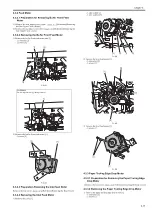
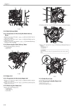
4.2.5 Stack Wall (Upper)
4.2.5.1 Removing the Stack Wall (Upper)
0020-8345
1) While holding the tray from the below, insert the driver [2] to the hole [1]
in the lower side, release the cam [3] as the direction of the arrow [A], lift
down the tray as the direction of the arrow [B] to the position that it does
not touch the stack wall (upper).
F-4-28
2) Remove the stack wall (upper) [1].
- 4 screws [2]
F-4-29
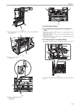
4.2.6 Stack Wall (Lower)
4.2.6.1 Preparation for Removing the Stack Wall (Lower)
0020-8346
1) Remove the stack wall (upper).
Reference[Removing the
Stack Wall (Upper)]
4.2.6.2 Removing the Stack Wall (Lower)
0020-8347
1) Open the front cover.
2) Remove the stopper (middle) [1].
- 1 screw [2]
F-4-30
3) Lift tray A and tray B in the position upper than stack wall (lower).
4) Lower the shutter [1], remove 2 screws [2].
5) Remove the stack wall (lower) [3].
- 4 screws [4]
F-4-31
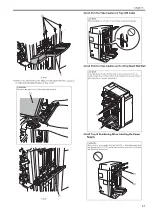
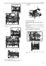
4.2.6.3 Install the Stack Wall (Lower)
0020-8348
1) Rotate the shutter drive shaft [2], hence the shutter drive roller [1] can
move down.
[1]
[A]
[B]
[2]
[3]
[1]
[2]
[2]
[1]
[2]
[4]
[3]
[1]
[2]
Summary of Contents for Saddle Finisher-AF2
Page 1: ...SERVICE MANUAL Saddle Finisher AF2 MARCH 6 2009...
Page 2: ......
Page 6: ......
Page 12: ...Contents...
Page 13: ...Chapter 1 Specifications...
Page 14: ......
Page 16: ......
Page 22: ......
Page 23: ...Chapter 2 Installation...
Page 24: ......
Page 26: ......
Page 55: ...Chapter 3 Functions...
Page 56: ......
Page 58: ......
Page 104: ...Chapter 3 3 46...
Page 105: ...Chapter 4 Parts Replacement Procedure...
Page 106: ......
Page 110: ......
Page 157: ...Chapter 4 4 47 F 4 213 3 2 1...
Page 158: ......
Page 159: ...Chapter 5 Maintenance...
Page 160: ......
Page 209: ...Chapter 5 5 47 F 5 221 SW382 SW381 SW383 ENTER SW384 SW385 DSP381 1...
Page 218: ......
Page 219: ...Appendix...
Page 220: ......
Page 221: ...General Timing Chart General Circuit Diagram Finisher Sorter DeliveryTray Saddle Finisher AF2...
Page 222: ......
Page 224: ......
Page 225: ...Contents 1 General Circuit Diagram 1 Signal Names 1 General Circuit Diagram 9...
Page 226: ......
Page 243: ......
Page 244: ......

