background image


(2) Periodic maintenance 

No periodic maintenance is necessary. 


(3) Periodic replacement parts 

There are no parts in this printer that require periodic replacement by a service engineer. 


(4) Replacement consumables 

There are no consumables that require replacement by a service engineer. 


1-2.  Customer Maintenance 

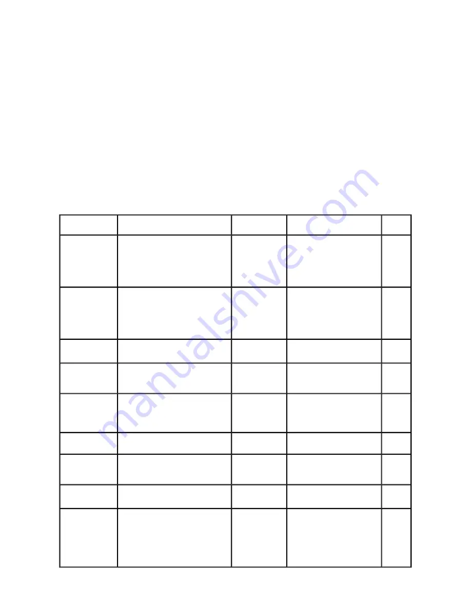
Adjustment

Timing

Purpose

Tool

Approx. 

time

Automatic print 
head alignment

- At print head replacement 

- When print quality is not satisfying, 

and not improved by print head 
cleaning. 

To secure the dot 
placement 
accuracy.

- 2 sheets of Matte Photo Paper 

(MP-101) 

- Printer buttons 

- Computer (automatic 

alignment via printer driver) 

13 min.

Manual print head 
alignment

- At print head replacement 

- When print quality is not satisfying, 

and not improved by print head 
cleaning. 

To secure the dot 
placement 
accuracy.

- 5 sheets of plain paper 

- Printer buttons 

- Computer (printer driver with 

the manual print head 
alignment selected) 

15 min.

Print head 
cleaning

When print quality is not satisfying.

To improve 
nozzle conditions.

- Printer buttons 

- Computer (printer driver) 

1 min.

Print head deep 
cleaning

When print quality is not satisfying, 
and not improved by print head 
cleaning.

To improve 
nozzle conditions.

- Computer (printer driver) 

2 min.

Ink tank 
replacement

When an ink tank becomes empty. 
("No ink error" displayed on the 
monitor, or short flashing of an ink 
tank LED)


2 min.

Paper feed roller 
cleaning

When paper does not feed properly.

To clean the 
paper feed rollers.

- Printer buttons 

2 min.

CD / DVD print 
position 
adjustment

At CD / DVD printing, when 
necessary.

To correct CD / 
DVD print 
position.

- Computer (application 

software) 

5 min.

Bottom plate 
cleaning

When the back side of the paper is 
smeared.

To clean the 
platen ribs.

- Plain paper 

- Computer (printer driver) 

1 min.

ASF sub- roller 
cleaning

When the paper fed from the ASF is 
smeared due to ink mist attached to the 
ASF sub-rollers.

To clean the ASF 
sub-rollers.

- Plain paper 

- Printer buttons 

See Part 2, 4. FAQ, How to 
make and set the ASF sub-
roller cleaning sheet, for 
details.


1 min.

Summary of Contents for PIXMA IP5300

Page 1: ...t When changes are made to the contents of the manual Canon will release technical information when necessary When substantial changes are made to the contents of the manual Canon will issue a revised edition The following do not apply if they do not conform to the laws and regulations of the region where the manual or product is used Trademarks Product and brand names appearing in this manual are...

Page 2: ...eshooting of the PIXMA iP5300 Part 2 Technical Reference New technology and technical information such as FAQ s Frequently Asked Questions of the PIXMA iP5300 Part 3 Appendix Block diagrams and pin layouts of the PIXMA iP5300 Reference This manual does not provide sufficient information for disassembly and reassembly procedures Refer to the graphics in the separate Parts Catalog I MANUAL OUTLINE ...

Page 3: ...3 3 Adjustment Settings 1 Paper feed motor adjustment 2 Grease application 3 Ink absorber counter setting 4 User mode 5 Service mode Service test print EEPROM initialization Ink absorber counter resetting Destination setting LF Eject correction Left margin correction 3 4 Verification Items 1 Service test print 2 EEPROM information print 4 MACHINE TRANSPORTATION Part 2 TECHNICAL REFERENCE 1 NEW TEC...

Page 4: ...2 2 Carriage Board Print Head Connector 3 PIXMA iP5300 SPECIFICATIONS II TABLE OF CONTENTS ...

Page 5: ...Part 1 MAINTENANCE PIXMA iP5300 TABLE OF CONTENTS ...

Page 6: ...t At paper feed motor replacement To adjust the belt tension Position the paper feed motor so that the belt is stretched tight None 5 min CD DVD detection sensor light volume correction At logic board replacement At carriage unit replacement To correct the light volume for the CD DVD detection sensor None Perform in the service mode 2 min Grease application At carriage unit replacement At lift cam...

Page 7: ...nment selected 15 min Print head cleaning When print quality is not satisfying To improve nozzle conditions Printer buttons Computer printer driver 1 min Print head deep cleaning When print quality is not satisfying and not improved by print head cleaning To improve nozzle conditions Computer printer driver 2 min Ink tank replacement When an ink tank becomes empty No ink error displayed on the mon...

Page 8: ... method referring to ISO IEC FCD24712 Note Ink yield may vary depending on texts photos printed applications software used print mode and type of paper used 1 4 Special Tools 1 5 Serial Number Location Black 1500 character pattern 8 400 pages Color 7 5 duty per color pattern 6 300 pages A4 photo borderless printing 400 pages 4 x 6 photo borderless printing 4 400 pages Postcard photo borderless pri...

Page 9: ...On the carriage flexible cable holder visible on the right of the carriage after the printer is turned on the top cover is opened and the carriage moves to the center Part 1 1 MAINTENANCE ...

Page 10: ...uide 1303 Error in the duplexing transport unit Paper jam in the under guide 1304 Error during paper feeding from the cassette Front door close error 1250 Open the paper output tray The error is indicated if the paper output tray is closed at start of a print job or while a print job is being performed 4 times Ink may have run out 1600 Replace the applicable ink tank or press the Resume Cancel but...

Page 11: ...310 Press the Resume Cancel button to eject the paper being used at error occurrence Printing will resume from on the front side of the next page Data which was to be printed on the back side of paper at error occurrence is skipped not printed 11 times Failed in automatic print head alignment 2500 Press the Resume Cancel button If paper is being fed at error occurrence the error is indicated after...

Page 12: ...sabled The error is indicated when no raw ink is detected and when the dot count number exceeds the threshold of complete exhaustion of ink Cycles of blinking in orange Alarm LED and green Power LED Error Solution Replacement of listed parts which are likely to be faulty 2 times Carriage error 5100 Carriage unit QM2 3999 Timing slit strip film QC1 6526 Logic board ass y QM3 0833 1 Carriage motor Q...

Page 13: ...feed cam sensor error 6B10 Sheet feed unit QM2 3902 Logic board ass y QM3 0833 1 15 times USB Host VBUS overcurrent 9000 Logic board ass y QM3 0833 1 16 times Pump roller sensor error 5C20 Logic board ass y QM3 0833 1 Purge unit QM3 0007 17 times Paper eject encoder error 6010 Timing sensor unit QM3 1271 Timing slit disk eject film QC2 0476 Logic board ass y QM3 0833 1 Paper feed motor QK1 1502 Pl...

Page 14: ...r ejected Replace the ink tank print head 2 or logic board ass y 1 Remove foreign material from the purge unit caps if any Replace the purge unit Printing is faint or white lines appear on printouts even after print head cleaning Line s not included in the print data appears on printouts Remove and re install the print head Replace the ink tank or print head 2 Perform print head alignment 3 Replac...

Page 15: ...101 For manual print head alignment plain paper can be used No ejection of black ink Replace the ink tank or print head 2 Remove foreign material from the purge unit caps if any Replace the purge unit Graphic or text is enlarged on printouts When enlarged in the carriage movement direction Clean grease or oil off the timing slit strip film Replace the timing slit strip film carriage unit or logic ...

Page 16: ...nt head alignment sensors 5 Check the ink system function See 3 3 Adjustment Settings 5 Service mode for details of 1 to 5 6 Perform LF Eject correction 7 Perform the print head alignment in the user mode 1 EEPROM information print Service test print Printing via USB connection Direct printing from a digital camera Ink absorber kit QY5 0179 After replacement 1 Reset the ink absorber counter See 3 ...

Page 17: ... DO NOT loosen them in other cases ii DO NOT loosen the red screws on both sides of the main chassis securing the carriage shaft positioning they are not adjustable in servicing Paper feed motor QK1 1502 The red screws securing the paper feed motor are allowed to be loosened DO NOT loosen any other red screws At replacement 1 Adjust the paper feed motor See 3 3 Adjustment Settings 1 Paper feed mot...

Page 18: ... Part 1 3 1 Notes on Service Part Replacement ...

Page 19: ...n Repair Servicing 1 External cover removal i Remove the paper support unit left photo and the main case cover right photo ii Remove the access cover iii Remove the side covers L and R Part 1 MAINTENANCE TABLE OF CONTENTS ...

Page 20: ...move 2 screws from the rear side v 1 Open the front door and the inner cover 2 Push the 2 arrow indicated portions to release the locks then lift the main case upward to remove it 3 Remove the interface cover ...

Page 21: ... 2 Door damper removal Door damper location Removal While pulling the claw upward to release the lock 1 in the photo below slide the damper to the left 2 in the photo below to remove it ...

Page 22: ...or can be removed easily 4 Printer unit removal The printer unit is fastened to the bottom case with 5 screws To remove the screw beneath the carriage unit in the home position unlock the carriage unit first as follows i Unlock the carriage unit Rotate the gear indicated by the red square toward the rear side of the printer 2 or 3 times The carriage will be unlocked ...

Page 23: ... the home position and remove the screw 5 Flexible cable and harness wiring connection Be cautious of wiring of the flexible cables and harness Improper wiring or connection may cause breakage of a line leading to ignition or emission of smoke ...

Page 24: ... i Logic board ass y wiring ii Paper feed motor side wiring Part1 3 2 Special Notes on Repair Servicing ...

Page 25: ... loosen them in other cases 2 Grease application Printer Unit Part 1 MAINTENANCE TABLE OF CONTENTS No Part name Where to apply grease oil Drawing No Grease oil Grease oil amount mg Number of drops x locations 1 Chassis ass y Entire surface the carriage slider contacts 1 Floil KG107A 27 to 54 3 x 1 2 Adjust plate L Carriage shaft cam L sliding portion 2 Floil KG107A 18 to 36 2 x 1 3 Chassis ass y C...

Page 26: ...Floil KG107A 9 to 18 1 x 1 10 Carriage shaft Carriage shaft surface where the carriage unit slides and where the machine application of the grease is not feasible 10 Floil KG107A 9 to 18 1 x 1 11 CL gear base Outer surface of the CL idle gear R cylinder 11 Floil KG107A 9 to 18 1 x 1 12 CL gear base Outer surface of the CL output gear cylinder 12 Floil KG107A 9 to 18 1 x 1 13 CL input gear Joint of...

Page 27: ......

Page 28: ... Part 1 3 3 Adjustment Settings 1 2 ...

Page 29: ...enance tab Print head deep cleaning Cleaning Black or Color separately or both Black and Color Perform from the printer driver s Maintenance tab Paper feed roller cleaning See Standalone printer operation below Nozzle check pattern printing See Standalone printer operation below Also available from the printer driver s Maintenance tab Print head alignment automatic manual See Standalone printer op...

Page 30: ...n half crosswise then unfold and set it in the ASF with the folded ridge facing down 6 times Unspecified 7 times Head to paper distance setting to the widest 8 times or more Unspecified Function Procedures Remarks Service test print Model name Destination ROM version USB serial number Ink absorber counter value ink amount in the ink absorber LF Eject correction value CD DVD sensor correction value...

Page 31: ...ft margin correction value Record of disabling the function to detect the remaining ink amount Ink absorber counter reset See Service mode operation procedures below If the ink absorber counter value is 7 or more replace the ink absorber kit LF Eject correction See Service mode operation procedures below Left margin correction See Service mode operation procedures below Destination settings See Se...

Page 32: ...cted Pattern No then press the Power button See the flowchart below 1 In the LF Eject correction mode press the Resume Cancel button the specified number of time s according to the paper to be used in LF Eject correction listed in the table below then press the Power button Set a sheet of selected paper in the ASF direction 10 times Green Power LF Eject correction 11 times Orange Alarm Left margin...

Page 33: ...ed 5 times or more then the Power button is pressed the printer returns to the service mode menu selection 2 The LF Eject correction pattern for the selected paper is printed LF correction values from 0 to 2 Eject correction values from 0 to 2 3 In the printout select the Pattern No in which streaks or lines are the least noticeable press the Resume Cancel button the same number of time s as the s...

Page 34: ...ght alternately Alarm in orange and Power in green If the Resume Cancel button is pressed 3 times or more then the Power button is pressed the printer returns to the service mode menu selection 4 The selected LF correction value or Eject correction value is written to the EEPROM The printer returns to the service mode menu selection after the correction values are written to the EEPROM Selected pa...

Page 35: ......

Page 36: ...jected After this set the correction value to the EEPROM in the steps below 2 Selection of the parameter mode for left margin correction Press the Resume Cancel button the specified number of time s according to the parameter mode listed in the table below then press the Power button Each time the Resume Cancel button is pressed the Alarm and Power LEDs light alternately Alarm in orange and Power ...

Page 37: ...tion in all the parameter modes is completed press the Resume Cancel button 4 times or more in the parameter mode selection then press the Power button to return to the service mode menu selection Number of times the Resume Cancel button is pressed N Left margin correction value 0 times Return to the parameter mode selection for left margin correction 1 time 1 pitch 2 times 2 pitches 3 times 3 pit...

Page 38: ......

Page 39: ......

Page 40: ... Part 1 3 3 Adjustment Settings 3 to 5 ...

Page 41: ...for horizontal dot mis alignment Ink shall be ejected from all nozzles Check 4 check pattern for irregular line feeding There shall be no remarkable streaks or unevenness Check 5 destination Check 6 LF correction value The value selected in the LF correction is printed in cyan Check 7 check pattern for LF correction the check pattern selected in the LF correction Check 8 check pattern for uneven p...

Page 42: ... Service test sample ...

Page 43: ......

Page 44: ...00 P NZedge 000 Q CbiHiReso 000 R MCbiHiReso 000 S SCbiCHiReso 000 T SCb MCfHiResoOffOw 000 U SCb MCfHiResoOffHo 000 a SCf MCbOffOw 000 b SCf MCbOffHo 000 c SCb CfOffOw 000 d SCb CfOffHo 000 e SCf CbOffOw 000 f SCf CbOffHo 000 g SCf MCbHiResoOffOw 000 h SCf MCbHiResoOffHo 000 i SCb CfHiResoOffOw 000 j SCb CfHiResoOffHo 000 k SCf CbHiResoOffOw 000 l SCf CbHiResoOffHo 000 CDIN PB 000 OPB 000 PAGE Al...

Page 45: ...ges PAGE total plain paper High Resolution Paper Matte Photo Paper Photo Paper Pro Photo Paper Plus Glossy Photo Paper Plus Semi gloss Glossy Photo Paper postcard envelope 22 U turn cassette feed pages total plain paper High Resolution Paper Matte Photo Paper Photo Paper Pro Photo Paper Plus Glossy Photo Paper Plus Semi gloss Glossy Photo Paper postcard envelope 23 Auto duplex print pages total Ph...

Page 46: ...tion 2 below Caution 1 If the print head is removed from the printer and left alone by itself ink the pigment based black ink in particular is likely to dry For this reason keep the print head installed in the printer even during transportation 2 Securely lock the carriage in the home position to prevent the carriage from moving and applying stress to the carriage flexible cable or causing ink lea...

Page 47: ...Part 2 TECHNICAL REFERENCE PIXMA iP5300 TABLE OF CONTENTS ...

Page 48: ...n The square form makes the printer look more compact and shorter in height 3 New support of DVD CD print function in Canada model DVD CD print function is now available in the Canada model as well as other models 4 Remaining ink amount indication sequence in 2006 products In previous models indication of the remaining ink amount differs between the individual ink tank system and the FINE cartridg...

Page 49: ...ot count exceeds the specified value Empty No raw ink is detected by the optical method and the dot count value exceeds the threshold of complete exhaustion of ink A warning will be displayed to indicate that ink has run out By pressing and holding the Resume Cancel button for 5 seconds or longer the function to detect the remaining ink amount can be disabled Unknown Raw ink remains but the dot co...

Page 50: ... Part 2 1 NEW TECHNOLOGIES ...

Page 51: ...d cleaning All in sequence 45 for the 3rd cleaning Black only Dot count cleaning Black When the specified number of dots are printed since the previous Black cleaning 0 20 Black 40 Black Timer cleaning 0 2 Black only If 24 to 504 hours have elapsed since the previous Black cleaning till the start of the next printing 0 20 Black 40 Black Timer cleaning 1 Black Color If 504 to 720 hours have elapsed...

Page 52: ...counted as well as its duration and capping or purging is performed according to the counted value to moisturize the nozzles During the capping operation the message is displayed on the monitor indicating printer maintenance is being performed The moisturizing timer calculates a total amount of the following 1 A period of time the print head moves from the standby position to the print head replac...

Page 53: ...Capping time 30 sec 60 sec 2 2 CLEANING MODE AND AMOUNT OF INK PURGED ...

Page 54: ...1 pass Bi PigBk C M Y Photo Paper Pro PR 101 Print quality Resolution HxV dpi Print control Ink used Standard C M Y k 1200X1200 C M c m 600X1200 3 5 passes Bi C M C M Y k c m Photo Paper Plus Glossy Photo Paper Plus Semi gloss PP 101 SG 101 Print quality Resolution HxV dpi Print control Ink used Standard C M Y k 1200X1200 C M c m 600X1200 3 5 passes Bi C M C M Y k c m Matte Photo Paper MP 101 Prin...

Page 55: ...1200X1200 5 passes Bi C M Y c m k Standard C M Y c m k 1200X1200 7 passes Bi C M Y c m k C Other photo paper Print quality Resolution HxV dpi Print control Ink used Standard C M Y k 1200X1200 C M c m 600X1200 8 passes Bi C M C M Y k c m Paper type Printer driver Custom setting 5 Fast 4 3 2 1 Fine Plain paper Print quality Resolution HxV dpi Print control Ink used Custom PigBk 300X300 1 pass Bi Pig...

Page 56: ... C M c m 600X1200 7 passes Bi C M C M Y k c m Photo Paper Plus Double Sided PP 101D Print quality Resolution HxV dpi Print control Ink used Standard C M Y k 1200X1200 C M c m 600X1200 5 passes Bi C M C M Y k c m High C M Y k 1200X1200 C M c m 600X1200 7 passes Bi C M C M Y k c m Other photo paper Print quality Resolution HxV dpi Print control Ink used Standard C M Y k 1200X1200 C M c m 600X1200 8 ...

Page 57: ...solution HxV dpi Print control Ink used High C M Y k 1200X1200 C M c m 600X1200 7 passes Bi C M C M Y c m k Photo Paper Plus Glossy Photo Paper Plus Semi gloss PP 101 SG 101 Print quality Resolution HxV dpi Print control Ink used High C M Y k 1200X1200 C M c m 600X1200 7 passes Bi C M C M Y c m k 2 3 PRINT MODE ...

Page 58: ...eding at the level of 1 Paper feeding from the ASF Credit Card size Since coaxial tolerance between the pinch roller and the LF roller which determines the paper feed alignment is 0 2mm skewed paper feeding can occur However according to the field data of current models the skewness level caused by the coaxial tolerance of 0 2mm is within the criteria of 1 thus the phenomenon is left as is Align t...

Page 59: ...side of paper Cleaning by user 1 Perform Bottom plate cleaning from the printer driver up to 3 times 1 2 If soiling on the paper still remains after 3 times of Bottom plate cleaning wipe the platen rib s and their surroundings with a cotton swab If the phenomenon persists after conducting 1 and 2 servicing is required Service Wipe any soiling or dirt off from the sheet feed unit and the bottom cas...

Page 60: ...lts Skewed paper feeding SG 101 Paper feeding from the ASF 10 sheets max set in the ASF When 10 sheets of paper are set in the ASF and if they curl significantly the curled portions of paper get over the cover guide not being aligned along the guide properly Straighten the paper Set 5 or less sheets of paper in the ASF Paper feeds at an angle A margin appears on printouts 8 A Operation Cannot inst...

Page 61: ...e in half 2 Fold the paper at approx 60 mm from the end and fold the folded end in half backward as shown below skipped or it was performed using plain paper paper usable 10 B Print results Uneven color Print head alignment is not effective to solve the problem Beyond the printer s ability Try a higher print quality setting though the print speed will become lower Color is uneven on printouts Stre...

Page 62: ...ver as shown below 4 Press and hold the Resume Cancel button until the Power LED blinks 3 times then release the button to perform the paper feed roller cleaning For details see Standalone printer operation Occurrence level A The symptom is likely to occur frequently Caution required B The symptom may occur under certain conditions but likeliness is assumed very low in practical usage C The sympto...

Page 63: ...Part 3 APPENDIX PIXMA iP5300 TABLE OF CONTENTS ...

Page 64: ...1 BLOCK DIAGRAM 1 1 iP5300 PDF file for print Part 3 APPENDIX TABLE OF CONTENTS ...

Page 65: ......

Page 66: ... Part 3 1 BLOCK DIAGRAM ...

Page 67: ...art 3 APPENDIX TABLE OF CONTENTS No Signal Name Function Input Output 1 AB_PWR AB power supply 2 AB_DATA AB data signal BUS 3 AB_PWR AB power supply 4 AB_CLK AB clock signal BUS 5 VSEN_CDRS Power supply for CDR sensor OUT 6 SNS_CDR_P CDR position sensor signal IN 7 THERMO CR temperature sensor signal IN ...

Page 68: ...al 1 Col 1 OUT 22 H_ENB3 Head heat enable signal 3 SCol OUT 23 H_D4 Head data C1 OUT 24 H_D2 Head data PBK1 OUT 25 H_D3 Head data PBK2 OUT 26 H_ENB0 Head heat enable signal 0 BK OUT 27 H_D5 Head data SC1 OUT 28 H_D7 Head data SM2 OUT 29 H_D1 Head data BK2 OUT 30 H_D0 Head data BK1 OUT 31 LOGIC_GND Logic ground 32 H_CLK Head data transfer clock signal OUT No Signal name Function Input Output 1 H_GN...

Page 69: ... Head drive power supply 24V OUT 11 to15 H_GND Head ground No Signal name Function Input Output 1 PW_CONT Power supply control signal OUT 2 VH_GND Head ground 3 VH Head power supply IN 4 VM_GND Motor ground 5 VM Motor power supply IN No Signal name Function Input Output 1 SNS_USB USB VBUS power supply sense IN 2 D USB D signal BUS 3 D USB D signal BUS 4 GND Ground 5 to 9 GND Ground No Signal name ...

Page 70: ...ame Function Input Output 1 VSEN_3 3V Power supply for sensor 3 3V OUT 2 GND Ground 3 SNS_PE PE sensor IN 4 LF_ENC_B LF encoder phase B IN 5 VSEN_3 3V Power supply for sensor 3 3V OUT 6 LF_ENC_A LF encoder phase A IN 7 GND Ground 8 EJ_ENC_B EJ encoder phase B IN 9 VSEN_3 3V Power supply for sensor 3 3V OUT 10 EJ_ENC_A EJ encoder phase A IN 11 GND Ground No Signal name Function Input Output 1 LED_B...

Page 71: ...Power supply for sensor 3 3V OUT 2 GND Ground 3 SNS_PE_PF PE PF sensor IN 4 GND Ground 5 VSEN_3 3V Power supply for sensor 3 3V OUT 6 APCL_ENC_A APCL encoder phase A IN 7 APCL_ENC_B APCL encoder phase B IN 8 GND Ground 9 VSEN_3 3V Power supply for sensor 3 3V OUT 10 PF_ENC_A PF encoder phase A IN 11 PF_ENC_B PF encoder phase B IN No Signal name Function Input Output 1 CR_M CR motor OUT 2 CR_MN CR ...

Page 72: ...round 10 HD0_K1 Head data BK1 OUT 11 HD1_K2 Head data BK2 OUT 12 HD3_PBk2 Head data PBk2 OUT 13 HENB1 Head heat enable signal 1 OUT 14 HD6_M2 Head data M2 OUT 15 HD12_SC2 Head data SC2 OUT 16 VSS Logic ground 17 18 B_GNDH Head ground 19 HD5_SC1 Head data SC1 OUT 20 HENB0 Head heat enable signal 0 OUT 21 HENB3 Head heat enable signal 3 OUT 22 HLAT Head data latch signal OUT 23 HD8_Y1 Head data Y1 O...

Page 73: ...l OUT 33 ROM_DIO O Head EEPROM data signal IN 34 HD11_M1 Head data M1 OUT 35 36 B_VH1_24V Head drive power supply 24V OUT 37 38 A_VH_24V Head drive power supply 24V OUT 39 HVDD_3 3V Head logic power supply 3 3V OUT 40 ROM_SK Head EEPROM serial clock signal OUT 41 B_DIA1 Diode sensor anode 1 IN 42 ROM_DIO I Head EEPROM data signal OUT 43 VHT Head drive power supply 24V OUT 44 45 B_VH2_24V Head driv...

Page 74: ...int mode type of paper used and device that the printer is connected to For reference Max speed Custom 5 Standard Black text plain paper FINE pattern 31ppm 14 8ppm Color plain paper FINE pattern 24ppm 11 6ppm Printing direction Bi directional uni directional Print width Max 203 2mm 216mm in borderless printing Interface Computer USB 2 0 Hi Speed Camera Direct PictBridge with a PictBridge supported...

Page 75: ...l regulations RoHS EU WEEE EU Korea Package Recycle Law Green Point Germany Energy Star Eco Mark Law on Promoting Green Purchasing Serial number location On the carriage flexible cable holder visible on the right of the carriage after the printer is turned on the top cover is opened and the carriage moves to the center Remaining ink amount detection Available detection by optical method and dot co...

Page 76: ... 3 3 PIXMA iP5300 SPECIFICATIONS ...

Reviews: