background image

CHAPTER 2  STANDARDS AND ADJUSTMENTS

2-3

c.

Adjusting the Mirror Position (optical length between No. 1 mirror and No. 2 mirror)

If you have replaced the scanner drive cable, you must adjust the mirror position, by changing

the position of the cable retainer of the No. 1 mirror mount.

Reference:

1.

As more and more copies are made, the cable tends to become slack, requiring adjustment.

2.

If the optical length between the No. 1 mirror and the No. 2 mirror is not correct, the horizontal
reproduction ratio will be wrong, causing poor sharpness or blurred images.

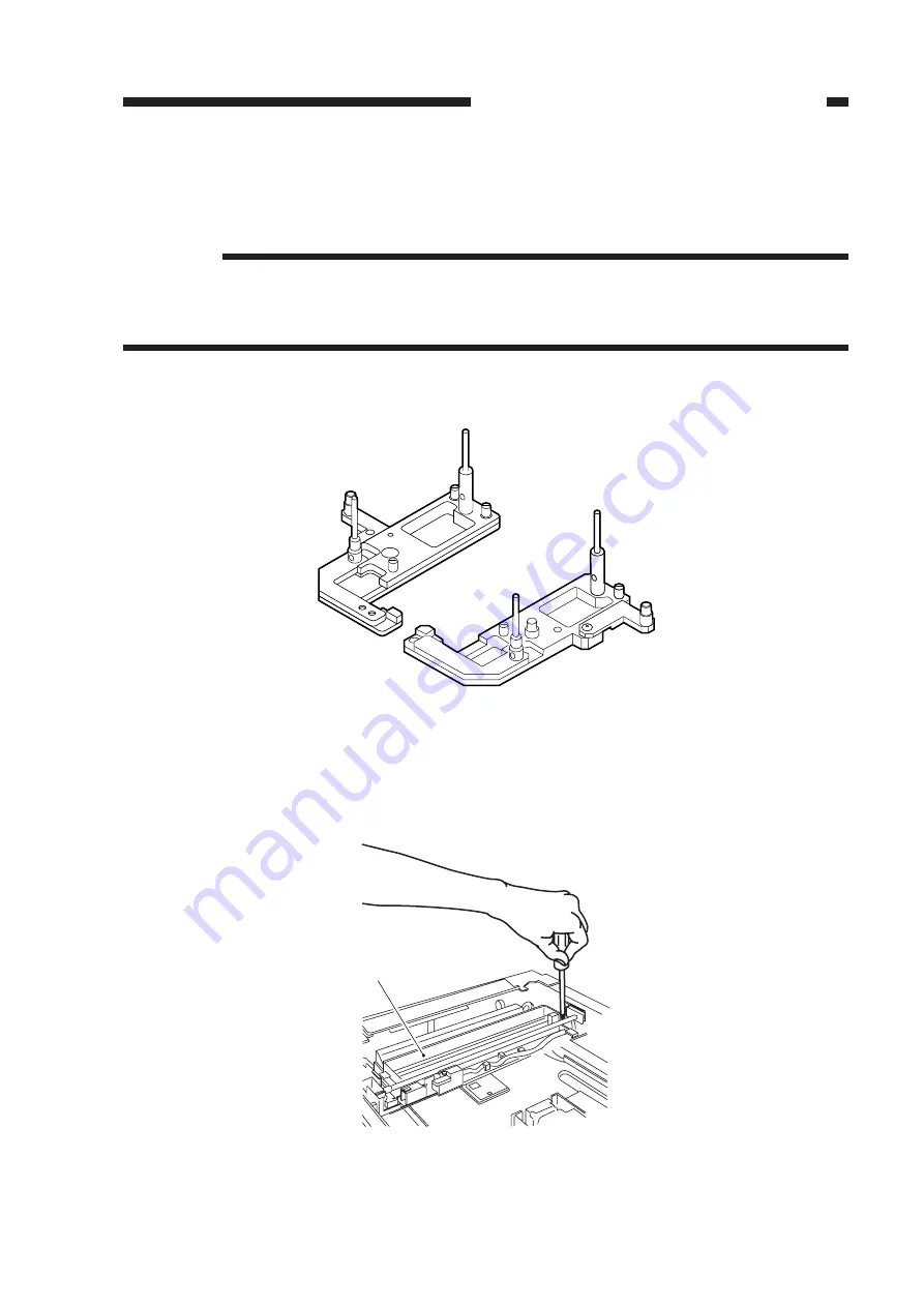
1) Fit the mirror positioning tool (FY9-3009) as shown.

Figure 2-5

2) Remove the copyboard glass.
3) Loosen the screws used to secure the cable retainer at the rear and the front of the No. 1 mirror

mount [1].

Figure 2-6

[1]

Summary of Contents for PC800 Series

Page 1: ...0 F13 8491 TYA00001 PC880 F13 8291 TZA00001 PC890 F13 8242 UAA00001 PC920 F13 8431 TVB00001 F13 8441 PUD00001 PUE00001 F13 8461 PUH00001 PC921 F13 8432 TVC00001 PC940 F13 8436 TVD00001 PC941 F13 8437 TVE00001 PC950 F13 8231 TVF00001 F13 8241 PUF00001 PUG00001 PC960 F13 8434 TVG00001 PC980 F13 8232 TVH00001 PC981 F13 8233 TVJ00001 ...

Page 2: ... OTHER PRINTED MATTER ANY QUESTIONS REGARDING INFORMATION CONTAINED HEREIN SHOULD BE DIRECTED TO THE COPIER SERVICE DEPARTMENT OF THE SALES COMPANY THIS DOCUMENTATION IS INTENDED FOR ALL SALES AREAS AND MAY CONTAIN INFOR MATION NOT APPLICABLE TO CERTAIN AREAS COPYRIGHT 1999 CANON INC Printed in Japan Imprimé au Japon Use of this manual should be strictly su pervised to avoid disclosure of confiden...

Page 3: ...Cassette 250 sheets 250 sheets 250 sheets Universal Universal Universal Universal Universal Universal Universal Universal Universal 500 sheets Universal 500 sheets 500 sheets Copying speed cpm at Direct 12 12 12 10 10 10 10 10 13 13 12 12 13 10 13 13 The notation indicates that the item in question is available This service handbook covers the models shown in the following table Be sure to have a ...

Page 4: ...i i ...

Page 5: ...oring and Handling the Cartridge with the Packaging Seal Removed 1 3 E Image Adjustment Basic Procedure 1 7 F Points to Note for Servicing 1 8 A Mechanical 2 1 B ADF 2 26 A Sensors and Solenoids 3 1 B Switches 3 2 C Lamp Heater Motor Etc 3 3 D PCBs 3 4 1 2 3 4 C Electrical 2 37 E ADF 3 5 F Variable Resistors VR and Check Pins by PCB 3 6 CHAPTER 4 SELF DIAGNOSIS A Self Diagnosis 4 1 APPENDIX A Gene...

Page 6: ......

Page 7: ...cally Replaced Parts The machine does not have parts which must be replaced on a periodical basis B Durables and Consumables The machine does not have items designated as durables or consumables C Scheduled Servicing The machine does not have any parts which require scheduled servicing 1 ...

Page 8: ...able 1 1 in addition keep the following in mind Avoid direct rays of the sun Avoid vibration Do not subject it to impact as by hitting or dropping it Table 1 1 Temperature Humidity Conditions for Storage Temperature between 20 C 4 F and 40 C 104 F Humidity 90 or less between 0 C 32 F and 35 C 95 F between35 C 95 Fand45 C 113 F between 20 C 4 F and 0 C 32 F from 40 C 104 F to 15 C 59 F from 20 C 4 ...

Page 9: ...priate storage box for storage 1 Storage after Removing the Packaging Seal a Avoid areas subject to the direct rays of the sun i e near a window Do not keep it in a car for a long time as it will be subjected to an extremely high temperature This applies even if the cartridge is inside a protective box b Avoid areas subjected to high or low temperature humidity or where temperature or humidity ten...

Page 10: ...t starts to run out of toner hold the cartridge level and shake it about 90 several times as shown in Figure 1 1 to even out the toner inside If you shake it in a different way the toner can spill out of the developing assembly or the cleaning assembly Figure 1 1 b Do not place the cartridge on its end or turn it over as shown in Figure 1 2 Figure 1 2 ...

Page 11: ...eans of protection If the drum is exposed to strong light for a long time however copies can start to show white spots or vertical bands Try leaving the machine alone as long as possible if such a problem is noted the memory i e cause of white spots or vertical bands however may not disappear Keep the following in mind Caution 1 Try to work briskly when removing a jam or replacing the cartridge 2 ...

Page 12: ......

Page 13: ...te 2 4 Fogging of background Note 2 NO YES Scanning system pickup feeding system delivery assembly Check the following 1 Cartridge 2 Scanning lamp 3 AE sensor PCB 4 DC controller PCB 5 Composite power supply PCB See the appropriate troubleshooting procedure Is the optimum density obtained by intensity adjustment Note 3 Can the deviation be corrected using the copy density correction switch SW101 N...

Page 14: ...ork remarks Multifeeder Pickup roller Cassette pickup roller Registration roller Transfer guide Moist cloth Moist cloth Cleaning Cleaning Cleaning Transfer charging roller Static eliminator Feed belt Lint free paper Special brush Moist cloth Cleaning Cleaning Cleaning Cleaning Moist cloth or alcohol Moist cloth or alcohol Moist cloth or alcohol Cleaning Do not use water or solvent Take care not to...

Page 15: ...n If you have performed this adjustment be sure to adjust the image leading edge margin Figure 2 1 1 Turn VR105 on the DC controller PCB so that the width is as indicated Figure 2 2 Table 2 1 Turing VR105 and Leading Edge Non Image Width Direction of VR105 Clockwise Counterclockwise Leading edge non image width Decreases Increases 2 0 1 5mm VR105 J102 J101 J107 J101 J131 VR103VR102 J103 J130 J114 ...

Page 16: ...ding edge non image width is as indicated before performing this adjustment Figure 2 3 1 Turn VR104 on the DC controller PCB so that the margin is as indicated Figure 2 4 Table 2 2 Direction of VR104 Clockwise Counterclockwise Image leading edge margin Increases Decreases Turing VR104 and Image Leading Edge Margin 2 5 1 5mm VR104 J102 J101 J107 J101 J131 VR103VR102 J103 J130 J114 J104 J105 J109 J1...

Page 17: ...ference 1 As more and more copies are made the cable tends to become slack requiring adjustment 2 If the optical length between the No 1 mirror and the No 2 mirror is not correct the horizontal reproduction ratio will be wrong causing poor sharpness or blurred images 1 Fit the mirror positioning tool FY9 3009 as shown Figure 2 5 2 Remove the copyboard glass 3 Loosen the screws used to secure the c...

Page 18: ...TANDARDS AND ADJUSTMENTS 2 4 4 Turn the cable drive pulley 3 so that the three shafts 2 of the mirror positioning tool for the front and the rear may be arranged as shown Figure 2 7 rear Figure 2 8 front 3 2 2 2 2 ...

Page 19: ...CHAPTER 2 STANDARDS AND ADJUSTMENTS 2 5 5 While keeping the condition of 4 tighten the positioning screw at the rear and the front of the No 1 mirror mount 1 Figure 2 9 rear Figure 2 10 front 1 1 ...

Page 20: ...ted check the force of the spring using a spring gauge CK 0054 and replace the spring if it is not as indicated Standard 970 150 g Making Measurements Push the spring gauge against the middle of the spring as shown and check to make sure that the reading of the spring gauge is 970 150 g when the holding plate is 18 mm away from the bottom of the cassette Figure 2 11 Spring gauge CK 0054 Holding pl...

Page 21: ...CHAPTER 2 STANDARDS AND ADJUSTMENTS 2 7 e 1 Routing the Scanner Drive Cable Figure 2 12 Wind 1 5 times black cable Wind 7 5 times silver colored cable ...

Page 22: ...he following Mirror positioning tool FY9 3009 Cable clip FY9 3017 Adhesive tape 1 Set the mirror positioning tool as shown Figure 2 13 2 Prepare about five strips of adhesive tape each one about 20 50 mm 3 Remove the copyboard glass 4 Disconnect the connectors J101 J131 1 from the DC controller PCB Figure 2 14 1 ...

Page 23: ... 2 9 5 If the machine is equipped with an ADF free the hook 2 and disconnect the two relay connec tors 3 from the left upper stay 4 Figure 2 15 6 Remove the three screws 5 and detach the left upper stay 4 Figure 2 16 2 2 2 2 3 3 4 5 4 5 ...

Page 24: ...CHAPTER 2 STANDARDS AND ADJUSTMENTS 2 10 7 Remove the four screws 7 and detach the lens cover 8 Figure 2 17 7 7 8 ...

Page 25: ...rsing Cable 1 Wind the reversing cables silver colored 2 on the cable drive pulley 1 7 5 times with the longer of the two on top then secure it in position with a cable clip 3 Figure 2 18 Figure 2 19 2 Shorter end Longer end 1 Face with a marking 1 3 Top view 3 ...

Page 26: ...able drive pulley 1 into the shaft 4 and secure it in position with an E ring 5 When putting the cable drive pulley into the shaft be sure that the hook is at the front Figure 2 20 3 Hook the shorter end 6 on the pulley 7 Figure 2 21 5 Hook front 1 4 7 6 ...

Page 27: ...ok it on the left rear pulley 10 and the pulley 11 of the No 2 3 mirror mount Figure 2 22 5 After fitting the shorter end 6 on the cable hook 12 secure its end with adhesive tape 13 Be sure that the secured end of the cable is found where the hole in the left side plate and the tip of the cable matches Figure 2 23 10 11 6 8 9 6 12 13 ...

Page 28: ...pulley 1 and hook it on the pulley 15 on the right front side Figure 2 24 7 Lead the longer end 14 under the No 1 mirror mount 8 and the No 2 3 mirror mount 9 then hook it on the pulley 16 on the left front side and the pulley 17 of the No 2 3 mirror mount Figure 2 25 14 15 1 8 17 9 16 14 ...

Page 29: ...ook the longer cable 14 on the cable hook 18 then secure its end to the left side with adhesive tape 19 Be sure that the secured end of the cable is found where the hole in the left side plate and the tip of the cable matches Figure 2 26 18 19 14 ...

Page 30: ... black 2 on the top hook of the cable drive pulley 1 and wind it 1 5 times Then secure the shorter end 3 as shown with adhesive tape 4 Figure 2 27 2 Lead the longer end 5 along the cable drive pulley 1 as shown and hook it on the pulley 6 on the right front side Figure 2 28 4 3 2 1 Face without a marking 5 6 1 ...

Page 31: ...d 5 under the No 1 mirror mount 7 then hook it on the pulley 8 of the No 2 3 mirror mount and lead it between the No 1 mirror mount 7 and the scanning lamp 9 Figure 2 29 4 Hook the end of the longer end 5 on the hole 10 on the right side Figure 2 30 5 7 8 9 5 10 ...

Page 32: ...ook it on the pulley 11 on the right rear side Figure 2 31 6 Lead the shorter end 3 under the No 1 mirror mount 7 and hook it on the pulley 12 of the No 2 3 mirror mount as shown then lead it between the No 1 mirror mount 7 and the scanning lamp 9 Figure 2 32 11 3 7 9 3 12 ...

Page 33: ...TS 2 19 7 Hook the end of the shorter end 3 on the hole 13 on the right side Figure 2 33 8 Free the shorter end 3 and the longer end 5 reversing cable and connect both with a spring 14 then fit the stopper 15 Figure 2 34 3 13 14 3 15 5 ...

Page 34: ...CHAPTER 2 STANDARDS AND ADJUSTMENTS 2 20 9 Detach the pulley clip 16 from the cable drive pulley 1 Figure 2 35 1 16 ...

Page 35: ...RDS AND ADJUSTMENTS 2 21 4 Positioning the No 1 Mirror Mount 1 Fix the rear and the front of the No 1 mirror mount 1 temporarily to the metal fixing 2 of the forwarding cable Figure 2 36 rear Figure 2 37 front 1 2 1 2 ...

Page 36: ...APTER 2 STANDARDS AND ADJUSTMENTS 2 22 2 Turn the cable drive pulley 4 so that the three shafts 3 of the mirror positioning tool for rear and front is as shown Figure 2 38 rear Figure 2 39 front 4 3 3 3 3 ...

Page 37: ...CHAPTER 2 STANDARDS AND ADJUSTMENTS 2 23 3 While keeping the condition of step 2 tighten the positioning screw on the rear and front of the No 1 mirror mount 1 Figure 2 40 rear Figure 2 41 front 1 1 ...

Page 38: ... manufacturer s name is toward the front Further be sure that the protrusion near its middle is as shown Figure 2 42 Caution If you have replaced the scanning lamp you must adjust the intensity of the lamp p 2 38 and perform AE adjustment Do not touch the lamp when handling it Logo mark Scanning lamp 45 approx mirror mount moving in reverse front ...

Page 39: ...ints to Note When Mounting the Fuse When mounting the thermal fuse of the No 1 mirror mount be sure that the fuse is oriented as shown Make sure that the fuse is in contact with the reflecting plate Figure 2 43 front Thermal fuse Reflecting plate ...

Page 40: ...ting the rear front original stop position 3 Adjusting the original leading edge stop position 2 Correcting Original Skew 1 Obtain a sheet of A4 or LTR white copy paper and draw two lines as indicated The sheet will be used as a test sheet Figure 2 44 2 Turn on the machine and place the test sheet prepared in step 1 on the original tray Figure 2 45 10mm 10mm A4 LTR copy papper ...

Page 41: ... standard or less Figure 2 46 5 If the difference is not as specified turn the adjusting screw found to the side of the left hinge unit to make adjustments Figure 2 47 Relationship between Adjusting Screw and L1 L2 Table 2 3 Direction of turn Clockwise Counterclockwise Relationship between L1 and L2 L1 L2 L1 L2 Copy image L1 L2 280mm L1 L2 0 1 8mm Adjusting screw ...

Page 42: ...ginal skew before adjusting the rear front original stop position 1 Obtain a sheet of A4 or LTR white copy paper and draw two lines as indicated The sheet will be used as a test sheet Figure 2 48 2 Remove the original tray cover from below the original tray Figure 2 49 10mm 10mm A4 LTR copy papper Original tray cover ...

Page 43: ...ine and place the test sheet prepared in step 1 on the original tray Figure 2 50 4 Press the Copy Start key to make a copy 5 Check to make sure that the distance L3 on the copy image indicated is 10 2 5 mm standard or less Figure 2 51 Copy image L3 L3 10 2 5mm ...

Page 44: ...d loosen the pinion gear positioning screw under the original tray and adjust the position of the pinion gear Figure 2 52 Relationship between Pinion Gear Position and L3 Table 2 4 Direction of pinion gear A B L3 Increases Decreases Pinion gear positioning screw Pinion gear A B ...

Page 45: ...e rear front original stop position before adjusting the original leading edge stop position 1 Obtain a sheet of A4 or LTR white copy paper and draw two lines as indicated The sheet will be used as a test sheet Figure 2 53 2 Remove the screw and remove the ADF controller cover Figure 2 54 10mm 10mm A4 LTR copy papper ADF controller cover Screw ...

Page 46: ...e and place the test sheet prepared in step 1 on the original tray Figure 2 55 4 Press the Copy Start key to make a copy 5 Check to make sure that the distance L4 on the copy image indicated is 10 2 0 2 5 mm standard or less Figure 2 56 Copy image L4 L4 10 2 0mm ...

Page 47: ...r PCB to ON and place an A4 or LTR white copy paper on the original tray Figure 2 57 7 Press the push switch PSW on the ADF controller PCB The copy paper will be picked up from the original tray and stopped on the copyboard glass Figure 2 58 0 F E D C B A 9 8 7 6 5 4 3 2 1 ON 1 2 ON 1 2 SW1 0 F E D C B A 9 8 7 6 5 4 3 2 1 ON 1 2 PSW ...

Page 48: ...ginal stop position by about 0 3 mm Press the push switch PSW after deciding on a position to discharge the copy paper and store the optimum value Figure 2 59 Relationship between Rotary Switch Direction and Original Position Table 2 5 Position shift of original Toward leading edge Toward trailing edge Direction of rotary switch Clockwise Counterclockwise 0 F E D C B A 9 7 6 5 4 3 2 1 ON 1 2 PSW S...

Page 49: ...r LTR white copy paper on the original tray 2 Shift bit 1 of the DIP switch SW1 on the ADF controller PCB to ON then push the push switch PSW to pick up the copy paper Figure 2 60 3 Turn the rotary switch SW2 on the ADF controller PCB clockwise by 10 notches Figure 2 61 0 F E D C B A 9 8 7 6 5 4 3 2 1 ON 1 2 ON 1 2 SW1 0 F E D C B A 9 7 6 5 4 3 2 1 ON 1 2 SW2 8 ...

Page 50: ...S AND ADJUSTMENTS 2 36 4 Press the push switch PSW on the ADF controller PCB The copy paper on the copyboard will be discharged and the optimum value will be stored Figure 2 62 0 F E D C B A 9 8 7 6 5 4 3 2 1 ON 1 2 PSW ...

Page 51: ...mp and execute AE adjustment Table 2 6 Adjustment 1 Intensity of the scanning lamp 2 AE mechanism 1 AE mechanism 1 Intensity of the scanning lamp 2 AE mechanism 1 Intensity of the scanning lamp 2 AE mechanism 3 Leading edge non image width 4 Image leading edge margin 5 Reproduction ratio fine adjustment 1 Excute original leading edge stop position ad justment Parts Scanning lamp AE sensor PCB Comp...

Page 52: ...he machine 2 Set the density correction switch SW101 to its middle index Figure 2 63 3 Turn off the AE mechanism and set the copy density adjusting lever on the control panel to its middle index 4 Place the Test Sheet on the copyboard and make a copy 5 Turn VR107 on the DC controller PCB gradually until gray scale No 9 is barely visible Figure 2 64 Table 2 7 VR107 and Copy Density Direction of VR1...

Page 53: ...ive sheets of white sheets of paper Be sure that the intensity of the scanning lamp has been adjusted when you have replaced the scanning lamp Set the density correction switch SW101 to the middle setting If the machine is not equipped with a density correction switch set the density adjusting lever to the middle set ting 1 Short JP103 and JP104 on the DC controller PCB Figure 2 65 2 While keeping...

Page 54: ...place five sheets of copy paper in its place then close the copyboard cover 8 Turn VR103 on the DC controller PCB so that the display will indicate 52 to 5c Figure 2 68 VR103 J102 J101 J107 J101 J131 VR103VR102 J103 J130 J114 J104 J105 J109 J106 J102 VR104 VR105 VR106 VR107 VR102 J102 J101 J107 J101 J131 VR103VR102 J103 J130 J114 J104 J105 J109 J106 J102 VR104VR105 VR106 VR107 VR103 J102 J101 J107...

Page 55: ...n VR103 fully counterclockwise and go back to step 5 and make adjustments once again 10 Make a copy and check to make sure that it is free of fogging and its text is adequately dark If the copy is foggy or its text is too light go back to step 1 and start over If the results of adjustment for a second time are not good make adjustments using the den sity correction switch SW101 Figure 2 69 SW101 L...

Page 56: ...Work Meter 1 Before replacing the DC controller PCB turn on the power then connect the meter probes to CP23 and GND on the DC controller PCB and measure the voltage probe CP23 probe GND Figure 2 70 2 After replacing the DC controller PCB measure the voltage as in step 1 then turn VR106 on the DC controller PCB so that the reading is the same as before replacement VR106 CP23 GND VR106 VR107 VR104 V...

Page 57: ...tration roller paper sensor RPD Checks During standby move the scanner by hand During standby move the lens mount by hand During standby move the detecting lever by hand During standby move the detecting lever by hand When the light block ing plate is at PS1 When the light block ing plate is not at PS1 When the light block ing plate is at PS2 When the light block ing plate is not at PS2 When the l...

Page 58: ......

Page 59: ...embly paper detection Vertical path assembly paper detection Single feeder paper detection Pre registration roller paper detec tion Pickup clutch solenoid Registration clutch solenoid Lens solenoid Multifeeder pickup solenoid Cassette pickup solenoid Symbol Name Photointerrupters Solenoid Notation PS1 PS2 PS3 PS4 PS5 Q751 SL1 SL2 SL3 SL4 SL5 Remarks Single feeder type only Multifeeder type only SL...

Page 60: ... ARRANGEMENT AND FUNCTIONS OF ELECTRICAL PARTS 3 2 B Switches Figure 3 2 Description Door switch Power switch Density correction switch Symbol Name Switch Switch Notation DS1 SW309 SW101 Remarks DS1 SW309 SW101 ...

Page 61: ...or Scanner cooling fan Fixing heater temperature detection Scanner temperature detection Lamp overheating detection Fixing heater overheating detection Fixing film varistor Transfer guide varistor Symbol Name Lamp Heater Motor Fan motor Thermistor Thermal fuse Varistor Notation LA1 H1 M1 M2 FM1 TH1 TH2 FU1 FU2 VZ1 VZ2 Remarks M M2 M1 FU1 LA1 FM1 VZ1 H1 VZ2 TH1 TH2 FU2 ...

Page 62: ...lamp Makes an electrical connection between the machine top and bottom Provides copying insurrections indications Detects paper in front of the registration roller Detects the density of originals Used for blanking exposure Used for blanking exposure Ref 1 2 3 4 5 6 7 8 9 Name Noise filter PCB DC controller PCB Composite power supply PCB High voltage contact PCB Control panel PCB Sensor PCB AE sen...

Page 63: ...tection Registration roller paper detection Original placement detection ADF open close switch Belt motor Pickup motor Controls sequence of operations Symbol 1 Name Photointerrupter Microswitch Motor ADF controller PCB Notation PI1 PI2 PI3 MS1 M1 M2 Remarks PS M2 PI3 PI2 M1 PI1 MS1 1 M Figure 3 5 ...

Page 64: ...not touch them in the field Caution VRs that may be used in the field VRs that must not be used in the field 1 DC Controller PCB Figure 3 6 2 Composite Power Supply PCB Figure 3 7 J130 J114 J102 J111 J201 J111 J108 3 1 2 1 2 8 1 9 1 JP102 JP101 1 6 1 7 1 19 18 2 5 3 1 5 1 2 1 6 SW101 J113 J132 J106 J109 1 J105 J104 6 7 1 J103 J107 J101 J131 8 1 1 4 1 11 VR104 VR106 VR105 VR107 VR103 VR102 CP23 GND...

Page 65: ...CHAPTER 3 ARRANGEMENT AND FUNCTIONS OF ELECTRICAL PARTS 3 7 3 ADF Controller PCB Figure 3 8 1 10 TP1 1 9 J5 1 8 4 J2 1 J1 CB1 2 1 J6 7 1 J3 FACE PSW SW1 SW2 1 2 ON Soldered side ...

Page 66: ......

Page 67: ...is faulty The thermal fuse FU2 has blown The DC controller PCB is faulty The composite power supply PCB is faulty The power switch is turned off and then on immediately after an error E000 E001 E002 E003 has occurred The temperature detected by the thermistor TH1 does not reach 65 C 1 5 sec after the Copy Start key has been pressed The temperature detected by the thermistor TH1 does not reach 150 ...

Page 68: ...main motor drive signal MMD 1 is being generated The actual output value of the compos ite power supply high voltage is differ ent from the setting value twice in succession The scanner home position is not detected within 10 sec after the scanner has turned on The scanner does not leave the home position after it has turned on The lens hoe position is not detected after the lens has moved the max...

Page 69: ...the thermistor has an open circuit 2 In the case of E0 E000 E001 E002 E003 or E220 the machine will turn off in 1 5 sec for E0 and E000 through E003 and in 2 sec for E220 3 In the case of E0 E000 E001 E002 or E003 perform the following steps 1 Turn off the power switch and short circuit JP101 and JP102 on the DC controller PCB with a screwdriver or the like Figure 4 1 2 While keeping the condition...

Page 70: ......

Page 71: ...ch solenoid SL1 Cassette pickup solenoid SL5 Vertical path roller paper sensor PS4 Registration clutch solenoid SL2 Pre registration roller paper sensor Q751 Scanning lamp LA1 Primary AC bias Primary DC bias Developing AC bias Fixing heater H1 Scanner cooling fan FM1 Delivery sensor PS3 Developing DC bias Transfer bias Static eliminator bias SCFW SCRV Scanner lens drive motor reverse APPENDIX A Ge...

Page 72: ...ette pickup solenoid SL5 Vertical path roller paper sensor PS4 Scanner cooling fan FM1 Pre registration roller paper sensor Q751 Scanning lamp LA1 Primary AC bias Primary DC bias Copier ADF Registration clutch solenoid SL2 Transfer bias Static eliminator bias Developing AC bias Developing DC bias Fixing heater H1 Delivery sensor PS3 Copy Start key ON Original set STBY INTR SCFW ORGST ORGST SCRV SC...

Page 73: ...VOLTAGE MONITOR signal PDP VERTICAL PATH ROLLER PAPER DETECTION signal PR_DC_ON PRIMARY CHARGING DC BIAS ON signal PUSLD PICKUP CLUTCH SOLENOID DRIVE signal PWM_1KHz SCANNING LAMP INTENSITY ADJUSTMENT signal PWOFF POWER SWITCH OFF signal RGSLD REGISTRATION CLUTCH SOLENOID DRIVE signal RLOFF RELAY DRIVE signal RPD PRE REGISTRATION ROLLER PAPER DETECTION signal SB_LP SIDE BLANK EXPOSURE LAMP ON sign...

Page 74: ......

Page 75: ...302 J213 J212 J209 BP704 BP702 BP703 BP701 BP706 BP707 BP705 J14 J15 VZ2 J13 SP TR J12 J11 PR DV J205 3 2 1 4 GND 24VU 1 3 2 4 M M1 J901 J2 2 1 J207 1 2 2 1 J434 2 1 J16 J15 H1 J17 FU2 FU1 FT6 FT5 LA1 DC CONTROLLER PCB COMPOSITE POWER SUPPLY PCB HVT BOARD 1 HVT BOARD 2 MAIN MOTOR DRIVER PCB SENSOR PCB SIDE BLANK EXPOSURE PCB CONTROL PANEL PCB Power switch NOISE FILTER PCB NOISE FILTER PCB AE SENSO...

Page 76: ...N ADFC OR OR 24V COM NO MS1 ADF Switch 4 2 1 3 6 5 7 4 2 1 3 5 6 7 J3 4 1 2 3 J5 5 6 7 8 9 1 2 4 3 5 7 6 8 9 ADF CONTROLLER PCB 4 4 2 1 3 2 1 3 5 5 M1 Belt motor 2 2 M1 Pickup motor 1 1 6 5 1 2 3 4 2 4 3 5 1 6 J105 PDP3 GY GND BL 5V BR PDP2 V GND BL 5V BR PDP1 Y GND BL 5V BR 2 3 1 J203 V BR BL PI3 sensor Original placement Registration sensor PI2 J202 2 3 1 Delivery sensor PI1 J201 2 3 1 V BR BL C...

Page 77: ...K 0054 Shape Tool Tool No Rank Remarks Spring gauge Mirror position ing tool pair for front and rear 1 FY9 3009 B For adjusting the dis tance between the No 1 and No 2 mirrors Wire clip 2 FY9 3017 B For fixing the scanner wire in place while ad justing its tension 3 B Rank A Each service person is expected to carry one B Each five or so service persons is expected to carry one C Each workshop is e...

Page 78: ... 20g Composition Hydrocarbon fluorine family Alcohol Surface active agent Hydrocarbon fluorine chlorine family Alcohol Mineral oil paraffin family Silicone oil Uses Cleaning e g glass plastic rubber parts external covers Cleaning e g metal oil or toner dirt Lubricating spring clutch Lubricating drive and friction parts scanner rail Name Alcohol Solvent Lubricating oil Lubricating oil ...

Page 79: ...um Table A 1 b Mechanisms Descriptions Indirect static reproduction Roller direct charging Slit moving light source Auto or manual Dry toner projection Cassette 1 pc Single feeder single feeder type Multifeeder multifeeder type Curvature separation static eliminator Flat heater Blade Center reference copyboard Item Reproduction Charging Exposure Copy density adjustment Development Pickup Separatio...

Page 80: ...ss label sheet 2 A4R LTRR recycled paper 64 to 80 g m2 A4R B5R eco pa per 80 g m2 A4R postcard 3 Double Sided Overlay Copying 5 Plain paper 64 to 128 g m2 colored paper business card 200 g m2 or less recycled paper 64 to 80 g m2 A4R B5R eco paper 80 g m2 A4R postcard 3 With claws Universal cassette 250 sheets of 80 g m2 paper A4 LGL to A5 STMT 250 sheet cassette 250 sheets of 80 g m2 500 sheet cas...

Page 81: ...only to single pickup if the multifeeder is used 3 Applies only to vertical feeding 4 Upon delivery be sure to remove each from the copy tray 5 Be sure to remove any curling before feeding for a second time 6 If stopped because paper ran out during copying operation 1 hr ...

Page 82: ...Type 484 9 448 2 297 5 mm 1 329 0 mm 2 19 1 in 17 6 in 11 7 in 1 13 0 in 2 ADF Type 484 9 448 2 358 3 mm 1 389 8 mm 2 19 1 in 17 6 in 14 1 in 1 15 3 in 2 Copyboard Type Single feeder type 19 3 kg 1 42 5 lb 1 20 9 kg 2 46 0 lb 2 Multifeeder type 19 5 kg 1 42 9 lb 1 21 1 kg 2 46 4 lb 2 ADF Type Single feeder type 23 8 kg 1 52 4 lb 1 25 2 kg 2 55 4 lb 2 Multifeeder type 24 0 kg 1 52 8 lb 1 25 4 kg 2 ...

Page 83: ...lt Ratios Table A 5 2R2E Inch AB configuration 1 1 000 1 0 707 1 0816 1 1 154 1 1 414 Item Direct Reduce I Reduce II Reduce III Reduce IV Enlarge I Enlarge II 3R1E Inch configuration 1 1 000 1 0 707 1 0 786 1 0 860 1 1 414 ...

Page 84: ...9 10 9 10 9 10 9 10 m 9 10 9 9 10 9 10 9 10 9 10 9 9 Copy size LTRR LGL STMTR MIN LGL LTRR MARJIN MAX A4R B5R A5R A4R A5R B5R A5R B5R A4R A5R A4R A4R B5R A5R A4R A5R B5R A5R B5R A4R A5R A4R LTRR LGL STMTR MIN LGL LTRR MARJIN MAX Reproduction ratio Direct Reduce I 70 7 Reduce II 78 6 Reduce IV 86 0 Enlarge II 141 4 Direct Reduce I 70 7 Reduce III 81 6 Enlarge I 115 4 Enlarge II 141 4 Direct Reduce ...

Page 85: ...C Width 474 mm 18 7 in 659 mm 25 9 in with the tray open Depth 394 mm 15 5 in Height 74 mm 2 9 in 216 mm 8 5 in with the tray open 5 kg 11 lb approx 24 VDC and 5 VDC from the host 40 W or less Temperature same as the host Humidity same as the host Item Original pickup Original orientation Original position Original separation Original type Stack Original processing mode Original size detection Mix...

Page 86: ......

Page 87: ...C800s 900s REV 0 AUG 1999 PRINTED IN JAPAN IMPRIME AU JAPON Prepared by Office Imaging ProductsTechnical Support Division CANON INC Printed in Japan REVISION 0 AUG 1999 30359 10317 5 1 Hakusan 7 chome Toride shi Ibaraki 302 8501 Japan ...

Page 88: ...0899AB1 31 1 PRINTED IN JAPAN IMPRIME AU JAPON This pubication is printed on 70 reprocessed paper ...

Reviews: