


CHAPTER 11 TROUBLESHOOTING
COPYRIGHT © 1999 CANON INC. CANON PC800s/900s REV.0 AUG. 1999 PRINTED IN JAPAN (IMPRIME AU JAPON)
11-6
b.
Image Leading Edge Margin (registration activation timing)
Make adjustments so that the leading edge margin is 2.5 ±1.5 mm when the Test Sheet is
copied.
Caution:
Be sure to check that the leading edge non-image width is as indicated before performing this
adjustment.
Figure 11-203
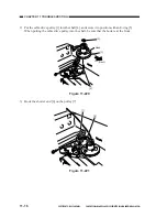
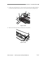
1) Turn VR104 on the DC controller PCB so that the margin is as indicated.
Figure 11-204
Table 11-202
Direction of VR104
Clockwise
Counterclockwise
Image leading edge margin
Increases
Decreases
Turing VR104 and Image Leading Edge Margin
2.5 ± 1.5mm
VR104
J102
J101
J107
J101
J131
VR103VR102
J103
J130
J114
J104
J105
J109
J106
J102
VR104VR105VR106
VR107
Summary of Contents for PC800 Series
Page 12: ......
Page 34: ......
Page 36: ......
Page 48: ......
Page 50: ......
Page 92: ......
Page 94: ......
Page 122: ......
Page 124: ......
Page 162: ......
Page 164: ......
Page 180: ......
Page 206: ......
Page 240: ......
Page 242: ......
Page 256: ......
Page 263: ......
Page 265: ......
Page 355: ......
Page 383: ......


