COPYRIGHT © 1998 CANON INC. CANON PC400/420/430,FC200/220 REV.0 JAN.1998 PRINTED IN JAPAN (IMPRIME AU JAPON)
CHAPTER 3 EXPOSURE SYSTEM
3-1
I. EXPOSURE/COPYBOARD DRIVE SYSTEM
A. Outline of Exposure System
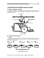
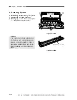
While the copyboard is moving forward, the scanning lamp (LA1 through LA8)
illuminates the document, and the reflected light is projected to the photosensitive drum
through the lens array.
Figure 3-101A
B. Copyboard Drive System
1. Outline
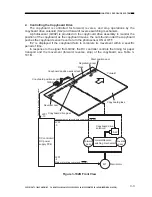
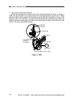
The copyboard is moved forward or in reverse by transmitting the drive of the main
motor (M1) to the copyboard drive gear (pinion). Figure 3-101B illustrates the
movement of the copyboard.
Photosensitive
drum
Scanning lamp
Copyboard glass
Lens array
Figure 3-101B Front View
Reverse
Forward
Reverse
Stop
Copier
Copyboard
Continuous copying
Copyboard Home
Position (HP)
Copyboard Start
Position (SP)
Copyboard Reversal
Position
Home
Position
1
2
3
4
5

