background image

– 23 –

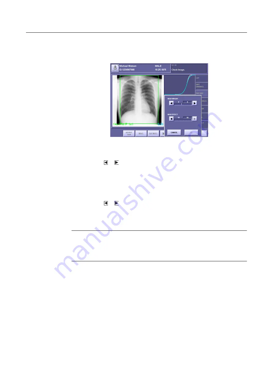
3.QA Mode Settings

3

Display the MORE window

Touch 

[MORE]

 to open the window.

MORE Window

4

Set the HIGH WEIGHT parameter

Touch the 

 or 

 button, and set the value within the range between 0 to 20.

The value on the left is the setting saved previously, and the value on the right is the cur-
rent setting.
For details of the parameter, refer to the step 3 in 

2.3.1 Setting DWT DEP for High-

Density Field (

 P.10)

 .

5

Set the HIGH EFFECT parameter

Touch the 

 or 

 button, and set the value within the range between 0 to 10.

The value on the left is the setting saved previously, and the value on the right is the cur-
rent setting.
For details of the parameter, refer to the 

step 4

 in 

2.3.1 Setting DWT DEP for High-

Density Field


(

 P.11)

.

NOTE:

If the HIGH EFFECT parameter is set to an excessive value, artifacts may 
occur, and the effective data of the exposure image may be damaged.
Check the exposure image, and if the results of compression appear to be too 
strong, either set the parameter to a smaller value, or set the DWT DEP not 
effective.

6

Set the settings valid, and close the MORE window

Touch 

[OK]

.

Summary of Contents for MLT (F)

Page 1: ...ng the instrument be sure to read this manual thoroughly Also read the manuals of other instruments in this system Keep the manual where it is easily accessible User s Manual MLT F CXDI Image Processing Software ...

Page 2: ...le for loss of image data due to any reason 2 Please have this product installed by Canon representative or distributor 3 Canon reserves the right to change the specifications of the product without prior notice CANON INC 2008 All rights reserved Under copyright laws this manual may not be copied in whole or in part without the written consent of Canon ...

Page 3: ...b 10 2 3 1 Setting DWT DEP for High Density Field 10 2 3 2 Setting DWT DEP for Low Density Field 11 2 4 Setting DWT NOISE R Tab 13 3 QA Mode Settings 14 3 1 Procedures to Change Parameters 14 3 2 Changing DWT ENHANCE Tab 17 3 3 Changing DWT DEP Tab 22 3 3 1 Changing DWT DEP for High Density Field 22 3 3 2 Changing DWT DEP for Low Density Field 24 3 4 Changing DWT Noise R Tab 26 4 QA Parameters 27 ...

Page 4: ......

Page 5: ...ETUP MENU button right Notation 2 If any detailed explanation for the operation or setting is available on other page in this manual the page to refer is indi cated with page number Example For details of the EFFECT parameter refer to the step 2 in 2 2 Setting DWT ENHANCE Tab P 7 Content On page 7 detailed description of the EFFECT feature is provided Notation 3 When description of the procedure o...

Page 6: ......

Page 7: ...tions provided with the CXDI series of Canon dig ital radiography system called CXDI in this manual By installing MLT F on the Control PC the advanced image processing features of MLT F are brought into full scope both in the Edit Exposure Mode and QA Mode The following examples show the QA Mode screens of CXDI System Software version 6 3 Standard QA Mode Screen DEP Tab QA Mode Screen Extended by ...

Page 8: ...itor is widened by decreasing the pixel value range in the second region of interest without changing the minute structures in the first region of interest DWT Noise Reduction P 13 The DWT NOISE R tab provides the function to reduce the noise components of the exposure image and improve it s granularity by specifying the two parameters the degree of enhancement EFFECT and upper limit of density PR...

Page 9: ... screen touch the followings SYSTEM EDIT EXPOSURE MODE Edit Exposure Mode Screen 2 Select the Sensor Unit If two or more sensor units are being used in the system touch the Sensor Unit button then select the Sensor Unit 3 Select the Category tab If eight or more categories are registered in the system touch the or button to dis play the Category tabs that are not currently visible Sensor Unit Butt...

Page 10: ... EDIT PARA screen appears EDIT PARA Screen first page 5 Display the next page Touch NEXT PAGE EDIT PARA Screen second page Availability of Frequency Processing Mode If your CXDI System Software is the version 5 0 or before there is no need to select the frequency processing mode as described in the next step step 6 Skip the step 6 and proceed to the step 7 ...

Page 11: ...Mode button to open the window then touch MLT F FREQUECY Frequency Processing Mode Window 7 Select the tab Touch the desired tab from among three tabs DWT ENHANCE DWT DEP DWT NOISE R DWT ENHANCE Screen 8 Set the parameters Set the parameters provided with the selected tab referring to the corresponding descrip tions 2 2 Setting DWT ENHANCE Tab P 7 2 3 Setting DWT DEP Tab P 10 2 4 Setting DWT NOISE...

Page 12: ...e the changed parameter Then touch OK When Password is required If the password is specified a different message is displayed in the window as follows Administrator s authority is needed Enter system password In this case touch anywhere within the frame to display On Screen Keyboard and type your password then touch OK ...

Page 13: ...and set the value within the range between 1 to 20 The value on the left is the setting saved previously and the value on the right is the cur rent setting The value indicates the degree of edge enhancement Select a larger value for higher degree of enhancement and select a smaller value for lower degree of enhancement NOTE If the EFFECT parameter is set to an excessive value artifacts may occur i...

Page 14: ...rom A or a To enhance the minute structure such as bone tissues select the Frequency Base that limits enhancement to the lower frequency and covers only the higher frequency The range decreases by excluding the lower frequency in descending order to A or a 4 Set the FREQUENCY BASE parameter Touch the desired Frequency Base button The parameter is set for the Frequency Base selected and the FREQUEN...

Page 15: ... the Low Density Field as the result of the enhancement the quality can be improved by selecting the Density Base that applies weaker density enhancement to the area where the degradation of quality is obvious 6 Set the DENSITY BASE parameter Touch the desired Density Base button The parameter is set for the Density Base selected and the DENSITY BASE window is closed ...

Page 16: ... left is the setting saved previously and the value on the right is the cur rent setting The value indicates the lower limit of density to start compression as shown in the fol lowing table Setting Values for Starting Density of High Density Field 3 Set the DEP WEIGHT parameter of the High Density Field Touch the or button and set the value within the range between 0 to 20 The value on the left is...

Page 17: ... intensity NOTE If the DEP EFFECT parameter is set to an excessive value artifacts may occur in the image or the effective data of the exposure image may be dam aged Check the exposure image and if the results of compression appear to be too strong either set the parameter to a smaller value or set the DWT DEP not effective 2 3 2 Setting DWT DEP for Low Density Field 1 Set the DWT DEP for the Low ...

Page 18: ...gree of compression and select a smaller value for lower degree of compression 4 Set the DEP EFFECT parameter of the Low Density Field Touch the or button and set the value within the range between 0 to 10 The value on the left is the setting saved previously and the value on the right is the cur rent setting The value indicates the intensity of restoration in high frequency component that reflect...

Page 19: ...value on the right is the cur rent setting Select a larger value for higher degree of noise reduction and select a smaller value for lower degree of noise reduction NOTE If the EFFECT parameter is set to an excessive value artifacts may occur in the image or the effective data of the exposure image may be damaged Check the output of exposure image and if the results of noise reduction appear to be...

Page 20: ...exposure On the Exposure screen touch the followings to display the DISPLAYING PARAME TER CHANGE QA SCREEN DURING EXPOSURE screen SYSTEM SETUP MENU SYSTEM SETUP DISPLAYING PARAME TER CHANGE QA SCREEN DURING EXPOSURE Then set the QA Mode screen effective To perform QA Processing right after x ray exposure Touch QA on the Preview screen To perform QA Processing after examination Select the exposure ...

Page 21: ... the desired tab from among three tabs DWT ENHANCE DWT DEP DWT NOISE R 4 Change the parameters Set the parameters provided with the selected tab referring to the corresponding descrip tions 3 2 Changing DWT ENHANCE Tab P 17 3 3 Changing DWT DEP Tab P 22 3 4 Changing DWT Noise R Tab P 26 When the Frequency Processing Mode button is not visible If the Frequency Processing Mode button is not displaye...

Page 22: ...Then touch YES 6 Close the QA Mode screen Touch OK When Password is required If the password is specified a different message is displayed as follows Administrator s authority is needed Enter system password In this case touch within the frame to display On Screen Keyboard and type your password then touch OK When OK is not visible on the screen If OK is not displayed on the screen touch the butto...

Page 23: ...th Parameters 2 Set the EFFECT parameter Touch the or button and set the value within the range between 1 to 20 The value on the left is the setting saved previously and the value on the right is the cur rent setting For details of the EFFECT parameter refer to the step 2 in 2 2 Setting DWT ENHANCE Tab P 7 NOTE If the EFFECT parameter is set to an excessive value artifacts may occur in the image o...

Page 24: ...of the FREQUENCY BASE parameter refer to the step 3 in 2 2 Setting DWT ENHANCE Tab P 8 FREQUENCY BASE Window 5 Select the FREQUENCY BASE parameter Touch the desired Frequency Base button The parameter is selected for the Frequency Base and the FREQUENCY BASE window is closed Touch the or button to display the buttons that are not currently visible FREQUENCY BASE Button DENSITYBASE Button ...

Page 25: ...ter the Frequency Base is set a bar graph is displayed at the top right of the screen to illustrate the comparisons with the frequency bands and degree of enhancement The horizontal axis labeled with Lv represents the frequency band indicating the lower frequency with a larger value The vertical axis represents the degree of enhancement indicating the stronger degree of enhancement with a larger v...

Page 26: ...enhancement degree on a line graph After the Density Base is set a line graph is displayed at the top right of the screen to illustrate the comparisons with density and the degree of enhancement The horizontal axis represents density and the vertical axis represents the degree of enhancement in each density indicating the stronger degree of enhancement with a larger value Line Graph of Enhancement...

Page 27: ...a to switch over the Frequency Base Graph bar graph and Density Base graph line graph Actual processing shall not be performed unless the DWT Edge Enhancement is effective although the graph is displayed on the screen Frequency Base Graph Bar Graph Density Base Graph Line Graph ...

Page 28: ...he or button and set the value within the range between 0 to 30 The value on the left is the setting saved previously and the value on the right is the cur rent setting For details of the parameter refer to the step 2 in 2 3 1 Setting DWT DEP for High Density Field P 10 Representation of DWT DEP on a graph A blue curve is always displayed on a graph and when HIGH DENS or LOW DENS is effective a wh...

Page 29: ...ch the or button and set the value within the range between 0 to 10 The value on the left is the setting saved previously and the value on the right is the cur rent setting For details of the parameter refer to the step 4 in 2 3 1 Setting DWT DEP for High Density Field P 11 NOTE If the HIGH EFFECT parameter is set to an excessive value artifacts may occur and the effective data of the exposure ima...

Page 30: ...nd set the value within the range between 0 to 30 range The value on the left is the setting saved previously and the value on the right is the cur rent setting For details of the parameter refer to the step 2 in 2 3 2 Setting DWT DEP for Low Density Field P 12 Representation of DWT DEP on a graph A blue curve is always displayed on the graph and when HIGH DENS or LOW DENS is effective a white cur...

Page 31: ...ch the or button and set the value within the range between 0 to 10 The value on the left is the setting saved previously and the value on the right is the cur rent setting For details of the parameter refer to the step 4 in 2 3 2 Setting DWT DEP for Low Density Field P 12 NOTE If the LOW EFFECT parameter is set to an excessive value artifacts may occur and the effective data of the exposure image...

Page 32: ...ly and the value on the right is the cur rent setting For details of the parameter refer to the step 2 in 2 4 Setting DWT NOISE R Tab P 13 NOTE If the EFFECT parameter is set to an excessive value artifacts may occur and the effective data of the exposure image may be damaged Check the output of exposure image and if the results of noise reduction appear to be too strong either set the parameter t...

Page 33: ...on the button n DENSITY BASE represented with the alphabet on the button If the DWT Edge Enhancement is not effective nothing is displayed The display values correspond to the actual values as shown in the following table Effect 4 DWT DEP The parameters are displayed as follows Dn STARTING DENSITY of High Density Field n DEP WEIGHT of High Density Field n DEP EFFECT of High Density Field n STARTIN...

Page 34: ...tical If image is not flipped nothing is displayed 8 Rotate The parameter is displayed as follows RTn Rotate Angle The degree of rotation is available from 90 90 180 If image is not rotated nothing is displayed Display Value 0 1 2 3 4 5 6 7 8 9 Density 0 2 0 3 0 4 0 5 0 6 0 7 0 8 0 9 1 0 1 1 Display Value 10 11 12 13 14 15 16 17 18 19 Density 1 2 1 3 1 4 1 5 1 6 1 7 1 8 1 9 2 0 2 1 Display Value 2...

Page 35: ...ined yet If the High Density Clipping Processing is not effective nothing is displayed 11 Dose Depend Processing D DEPEND MTF IMP One of the following parameters is displayed M0 Processing is not performed M1 Processing is performed in the fix mode M2 n n Processing is performed in the dose dependent mode The parameters for M2 are displayed as follows M2 n FILTER TYPE Index n INTENSITY Index The d...

Page 36: ......

Page 37: ......

Page 38: ......

Page 39: ......

Page 40: ...pan Telephone 81 3 3758 2111 CANON U S A INC CANON MEDICAL SYSTEMS 15955 Alton Parkway Irvine CA 92618 3616 U S A Telephone 1 949 753 4160 CANON EUROPA N V Medical Products Division Bovenkerkerweg 59 61 1185 XB Amstelveen The Netherlands Telephone 31 20 545 8926 PUB L IE 4081F ...

Reviews: