background image

53

APPENDIX

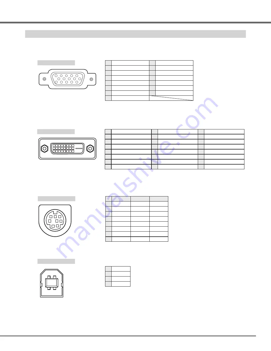
CONFIGURATIONS OF TERMINALS

COMPUTER INPUT-1 and MONITOR OUT TERMINALS (ANALOG)

Terminal : HDB15-PIN 

5

1

2

3

4

10

9

6

7

8

15

14

13

11

12

Red Input

Ground (Horiz.sync.)

Green Input

Sense 2

Blue Input

Ground (Red)

Ground (Green)

Ground (Blue)

1

5

2

4

3

6

7

8

+5V Power

Horiz. sync.

Ground (Vert.sync.)

DDC Data

Sense 0

Vert. sync.

DDC Clock

9

13

10

12

11

14

15

Pin Configuration

Terminal : Mini DIN 8-PIN

1

2

3

4

5

8

7

6

Pin Configuration

CONTROL PORT CONNECTOR

-----

CLK

DATA

GND

-----

-----

GND

-----

R X D

-----

-----

GND

RTS / CTS

T X D

GND

GND

-----

ADB

-----

GND

-----

-----

-----

GND

PS/2

Serial

ADB

1

2

3

4

5

6

7

8

COMPUTER INPUT-1 TERMINAL (DIGITAL)

Terminal : DVI 24-pin 

1

9

17

2

10

18

3

11

19

4

12

20

5

13

21

6

14

22

7

15

23

8

16

24

T.M.D.S. Data2–

No Connect

T.M.D.S. Data2+

No Connect

T.M.D.S. Data2 Shield

DDC Clock

DDC Data

No Connect

1

5

2

4

3

6

7

8

Pin Configuration

T.M.D.S. Data1–

No Connect

T.M.D.S. Data1+

No Connect

T.M.D.S. Data1 Shield

+5V Power

Ground (for +5V)

Hot Plug Detect

9

13

10

12

11

14

15

16

T.M.D.S. Data0–

No Connect

T.M.D.S. Data0+

No Connect

T.M.D.S. Data0 Shield

T.M.D.S. Clock Shield

T.M.D.S. Clock+

T.M.D.S. Clock–

17

21

18

20

19

22

23

24

Vcc

- Data

+ Data

Ground

1

2

3

4

USB CONNECTOR (Series B)

Pin Configuration

2

3

4

1

Summary of Contents for LV-7565F

Page 1: ...E English Multimedia Projector Owner s Manual LV 7565LV 7565F ...

Page 2: ...osition If not it may result in a fire hazard Provide appropriate space on the top sides and rear of the projector cabinet for allowing air circulation and cooling the projector Minimum clearance must be maintained If the projector is to be built into a compartment or similarly enclosed the minimum distances must be maintained Do not cover the ventilation slot on the projector Heat build up can re...

Page 3: ...is provided Never push objects of any kind into this projector through cabinet slots as they may touch dangerous voltage points or short out parts that could result in a fire or electric shock Never spill liquid of any kind on the projector This projector should be operated only from the type of power source indicated on the marking label If you are not sure of the type of power supplied consult y...

Page 4: ...ment generates uses and can radiate radio frequency energy and if not installed and used in accordance with the instructions may cause harmful interference to radio communications However there is no guarantee that interference will not occur in a particular installation If this equipment does cause harmful interference to radio or television reception which can be determined by turning the equipm...

Page 5: ...VEL SELECT 32 PICTURE SCREEN ADJUSTMENT 33 SETTING MENU 37 OPERATING WIRELESS MOUSE 41 MAINTENANCE 42 WARNING TEMP INDICATOR 42 AIR FILTER CARE AND CLEANING 43 CLEANING PROJECTION LENS 43 LAMP REPLACEMENT 44 LAMP REPLACE COUNTER 45 TROUBLESHOOTING 46 INDICATORS AND PROJECTOR CONDITION 48 COMPATIBLE COMPUTER SPECIFICATION 49 MENU TREE 50 TECHNICAL SPECIFICATIONS 52 CONFIGURATIONS OF TERMINALS 53 OP...

Page 6: ...ipment Supports a wide range of installation methods including ceiling mount stand alone and rear projection Silent Mode is provided for increasing lamp life and reducing power consumption Supports NTSC NTSC4 43 PAL SECAM PAL M and PAL N Equipped with a component video input terminal for playing DVD and HDTV with superb video quality Digital Visual Interface DVI D Equipped with DVI D to display th...

Page 7: ...ing power of Cooling Fans FRONT OF CABINET LAMP COVER ADJUSTABLE FEET AND FEET LOCK LATCHES PROJECTION LENS SPEAKERS INFRARED REMOTE RECEIVER LENS COVER POWER CORD CONNECTOR EXHAUST VENT TERMINALS AND CONNECTORS TOP CONTROLS AND INDICATORS INFRARED REMOTE RECEIVER CARRYING HANDLE AIR INTAKE VENT This projector is equipped with cooling fans for protection from overheating Pay attention to following...

Page 8: ...plug AC Power Cord when an appliance is not used When this projector is connected to the outlet with AC Power Cord an appliance is in Stand by Mode and consumes a little electric power CONNECTING AC POWER CORD Connect AC Power Cord supplied to a projector The AC outlet must be near this equipment and must be easily accessible To the POWER CORD CONNECTOR on the projector Projector side AC Outlet si...

Page 9: ...e quality It is recommended to limit ambient lighting in order to provide best image Min Zoom Max Zoom 100 77 11 8 3 6m 150 115 17 7 5 4m 200 154 24 0 7 3m 250 192 30 2 9 2m 300 231 36 1 11 0m 400 308 48 3 14 7m 10 0 1 1 LENS SHIFT ADJUSTMENT Projection lens can be moved up and down with motor driven lens shift function This function makes it easy to provide projected image where you want U D rati...

Page 10: ...ten ADJUSTABLE FEET lift front of a projector and pull and undo FEET LOCK LATCHES Position and keystone distortion of image can be adjusted using Menu Operation Refer to P 21 and 37 3 INSTALLING PROJECTOR IN PROPER POSITION Install the projector properly Improper installation may reduce the lamp lifetime and cause a fire hazard 10 10 Do not tilt the projector more than 10 degrees above and below D...

Page 11: ...nsport service in an unsuitable transport case This may cause damage to a projector To transport a projector through a courier or transport service consult your dealer for best way MOVING PROJECTOR Use Carry Handle when moving a Projector When moving a projector replace lens cover and retract feet to prevent damage to lens and cabinet When this projector is not in use for an extended period put it...

Page 12: ... to 14 and connect properly This projector uses a micro processor to control this unit and rarely this micro processor may malfunction and need to be reset This can be done by pressing RESET button with a pen which will shut down and restart unit Do not use RESET function excessively RESET BUTTON USB CONNECTOR Series B Do not press this button This button is used for our optional accessories Conne...

Page 13: ...er cords of both a projector and external equipment should be disconnected from AC outlet Turn a projector and peripheral equipment on before computer is switched on USB port MAC Adapter Set slide switches according to chart below VGA Cable HDB 15 pin DVI Digital Cable for Single Link T M D S BNC Cable Control Cable for Serial Port Control Cable for PS2 Port or ADB Port USB Cable MAC Adapter When ...

Page 14: ... RCA x 2 AUDIO IN S VIDEO Y Cb Pb Cr Pr VIDEO Component video output equipment such as DVD player or high definition TV source Composite Video Output Component Video Output Y Cb Pb Cr Pr Component Video Output Y Cb Pb Cr Pr Y Cb Pb Cr Pr Video Cables RCA x 1 or RCA x 3 BNC Cable Audio Output Composite Video Output VIDEO Video Cable RCA x 1 or RCA x 3 BNC Cable S VIDEO Cable Audio Cable RCA x 2 Aud...

Page 15: ...ose specified herein may result hazardous radiation exposure Laser Light Window These caution labels are put on the remote control LASER POINTER FUNCTION Used to select input source P23 24 30 Used to execute the selected item or to expand or compress the image in DIGITAL ZOOM mode P29 It is also used as a PC mouse in Wireless Mouse Operation P41 POWER ON OFF BUTTON Used to turn projector on or off...

Page 16: ...nt Remote Control Unit toward projector Receiver Window whenever pressing any button Maximum operating range for Remote Control Unit is about 16 4 5m and 60 in front and rear of the projector 16 4 5 m 60 16 4 5 m Used to adjust zoom P21 VOLUME POWER FOCUS ZOOM D ZOOM MENU MUTE LASER KEYSTONE NO SHOW FREEZE AUTO PC ADJ IMAGE P TIMER INPUT BRIGHT LENS SHIFT MUTE BUTTON Used to mute sound P22 ZOOM BU...

Page 17: ...of projection lamp draws to an end P44 Flashes red when internal projector temperature is too high P42 Used to select input source P23 24 30 Used to select an item or adjust value in ON SCREEN MENU They are also used to pan image in DIGITAL ZOOM mode P29 POINT LEFT RIGHT buttons are also used as VOLUME buttons Used to execute the selected item It is also used to expand compress image in DIGITAL ZO...

Page 18: ... display ON SCREEN MENU MENU BAR A red frame is POINTER Move POINTER red frame to MENU ICON that you want to select by pressing POINT RIGHT LEFT buttons Adjust ITEM DATA by pressing POINT RIGHT LEFT buttons Refer to following pages for details of respective adjustments Press POINT UP DOWN button and move POINTER red frame or red arrow to ITEM that you want to adjust and then press SET button to sh...

Page 19: ...o P23 IMAGE ADJUST MENU Used to adjust computer image Contrast Brightness Color Tint Color management Auto picture control Color temp White balance R G B Sharpness Gamma Noise reduction Progressive Refer to P34 36 PC ADJUST MENU Used to adjust parameters to match with input signal format Refer to P25 27 INPUT MENU Used to select input source Input 1 Input 2 or Input 3 Refer to P30 IMAGE SELECT MEN...

Page 20: ...Indicator is flashing projector cannot be turned on refer to the section MAINTENANCE on page 42 When the both WARNING TEMP and READY Indicator flashing refer to the section MAINTENANCE on page 42 1 Complete peripheral connections with Computer VCR etc before turning on projector Refer to CONNECTING TO PROJECTOR on pages 12 14 for connecting that equipment 3 When projector has cooled down READY Ind...

Page 21: ...stone dialog box appears 2 Correct keystone distortion by pressing POINT UP DOWN LEFT RIGHT button s Press POINT UP button to reduce the upper part of the image and press POINT DOWN button to reduce the lower part Press POINT LEFT button to reduce the left part and press POINT RIGHT button to reduce the right part Reduce the upper width with POINT UP button Reduce the lower width with POINT DOWN b...

Page 22: ...again or press Volume button s To increase volume press POINT RIGHT button and press POINT LEFT button for decreasing Press POINT LEFT RIGHT button s to switch built in speaker on and off Press POINT UP DOWN button to move a red frame pointer to item that you want to select and then press SET button Close SOUND Menu SOUND ADJUSTMENT DIRECT OPERATION MENU OPERATION Volume Built in SP Indicates roug...

Page 23: ...ove a red frame pointer to INPUT Menu icon Press POINT UP DOWN button and a red arrow icon will appear Move arrow to INPUT source that you want to select and then press SET button 1 2 Move a pointer to source and press SET button Source Select Menu INPUT Menu icon INPUT Menu icon Move a pointer red arrow to Input 1 and press SET but ton RGB PC Digital RGB Scart When video equipment is connected to...

Page 24: ...DOWN button to move a red arrow pointer to system that you want to set and then press SET button 1 2 PC SYSTEM MENU This projector automatically selects PC system among those provided in this projector and PC system can be also selected manually AUTOMATIC MULTI SCAN SYSTEM Press MENU button and ON SCREEN MENU will appear Press POINT LEFT RIGHT button to move a red frame pointer to INPUT Menu icon ...

Page 25: ...Unit PC ADJUST MENU Auto PC Adj Store adjustment parameters Adjustment parameters from Auto PC Adjustment can be memorized in this projector Once parameters are memorized setting can be done just by selecting Mode in PC SYSTEM Menu P24 Refer to step 3 of MANUAL PC ADJUSTMENT section P27 NOTE Fine sync Total dots and Picture Position of some computers can not be fully adjusted with this Auto PC Adj...

Page 26: ... icon 1 2 Press POINT UP DOWN button to move a red frame pointer to item that you want to adjust and then press SET button Adjustment dialog box will appear Press POINT LEFT RIGHT button to adjust value Adjusts an image as necessary to eliminate flicker from display Press POINT LEFT RIGHT button to adjust value From 0 to 31 Fine sync Adjust the number of total dots in one horizontal period Press P...

Page 27: ...e free Vacant Mode Shows values of Total dots Horizontal Vertical Display area H and Display area V Store icon Mode free icon Close this dialog box To store adjustment data To clear adjustment data To clear adjustment parameters previously set move a red frame pointer to Mode free icon and then SET button Move a red arrow pointer to Mode that you want to clear and then press SET button Display are...

Page 28: ...Standard High contrast and Custom by pressing IMAGE button on Remote Control Unit IMAGE button Standard High contrast Custom Normal picture adjustment preset on this projector Picture adjustment improved in reproduction of halftones This adjustment is suitable for providing better image in brighter place User preset picture adjustment in IMAGE ADJUST Menu P36 Standard High contrast Custom Move a r...

Page 29: ...u P24 Wide cannot be selected when 720p HDTV 1035i HDTV or 1080i HDTV is selected on PC SYSTEM Menu P24 This projector cannot display any resolution higher than 1280 X 1024 If your computer s screen resolution is higher than 1280 X 1024 reset resolution to lower before connecting projector Image data in other than XGA 1024 x 768 is modified to fit screen size in initial mode Panning function may n...

Page 30: ... to Video or Y Pb Cb Pr Cr and press SET button Source Select Menu Press POINT UP DOWN button to move a red arrow pointer to Input 3 and then press SET button Source Select Menu will appear 2 When video input signal is connected to Y Pb Cb Pr Cr jacks select Y Pb Cb Pr Cr Y Pb Cb Pr Cr When video input signal is connected to VIDEO jack select Video Video When connecting to those equipment select a...

Page 31: ...oming Video signal and adjusts itself to optimize its performance When Video System is 1035i or 1080i select system manually first If projector cannot reproduce proper video image it is necessary to select a specific component video signal format among 480i 575i 480p 575p 720p 1035i and 1080i Auto COMPONENT VIDEO SIGNAL FORMAT VIDEO JACK OR S VIDEO JACK Y Pb Cb Pr Cr JACKS Projector automatically ...

Page 32: ...l preset on this projector Standard Picture level adjusted for picture with fine tone Cinema User preset picture adjustment in IMAGE ADJUST Menu P36 Custom IMAGE LEVEL SELECT DIRECT Select image level among Standard Cinema and Custom by pressing IMAGE button on Remote Control Unit Normal picture level preset on this projector Standard Picture level adjusted for picture with fine tone Cinema User p...

Page 33: ... frame pointer to SCREEN Menu icon Press POINT UP DOWN button and move a red frame pointer to function that you want to select and then press SET button 1 2 NOTE SCREEN Menu cannot be operated when 720p 1035i or 1080i is selected on AV SYSTEM Menu P31 SCREEN MENU Provides image at a wide screen ratio of 16 9 Wide Provides image at a normal video aspect ratio of 4 3 Normal Move red frame to functio...

Page 34: ... for each image There are preset images for VIDEO mode and preset images for PC giving a total of two images 1 Press the POINT UP DOWN button to move the red frame point er to COLOR MANAGEMENT and then press the SET button The COLOR MANAGEMENT menu will appear and pointer mode will be enabled The image that was being projected when the button was pressed will be paused and the COLOR MAN AGEMENT PO...

Page 35: ...L COLOR SELECTION MODE The mode will return to the pointer mode even if you press the MENU key on the projector or the remote control You will need to reselect and re adjust the color in this case QUIT The COLOR MANAGEMENT menu will be exited and the display will return to the normal projection screen but any settings that have been changed will not be stored To store the changed settings be sure ...

Page 36: ...ure L2 Progressive scan mode to ON for still picture If you watch the old videotape with many noises press POINT LEFT RIGHT button s to change noise reduction mode Dialog box display is changed to On to reduce noise rough parts of image Press POINT LEFT RIGHT button s again to change noise reduction mode to off Noise reduction Progressive scan Color temp Press either POINT LEFT button or POINT RIG...

Page 37: ...Italian Spanish Portuguese Dutch Swedish Russian Chinese Korean and Japanese SETTING Menu icon Set a red frame pointer to item and press SET button Lamp mode Aspect V Aspect H When selecting the Lamp mode the projector reduce the brightness and set into the low power consumption mode Normal mode Auto mode Silent mode The brightness is adjusted automatically to a level that is suitable for the scre...

Page 38: ...screen Ceiling function Rear function Press SET button at this icon to display other items Press SET button at this icon to display previous items When this function is On the screen image is forcibly changed to a 4 3 image even if the input signal is HDTV This function is used to adjust the on screen menu display position When a SET button is pressed the adjustment screen is displayed arrows appe...

Page 39: ...e input signal is interrupted and any button is not pressed for 30 seconds or more the power management function operates in order to reduce power consumption and conserve lamp operating time The factory default settings for power management are Ready and 5 Min OPERATION 1 If the input signal is interrupted and any button is not pressed for 30 seconds or more the message No signal and the timer di...

Page 40: ...t and then press SET button The message Return to Factory default is displayed Move the pointer to Yes and then press SET button Another confirmation dialog box appears and select Yes and then press SET button Return the projector to Factory default This function returns all setting values except for the lamp counter to the factory default settings This locks operation of the projector s control p...

Page 41: ...ol Unit as Wireless Mouse for a Personal Computer installation of the mouse driver not supplied is required Make sure that the mouse driver is properly installed in your computer And make sure that the mouse port or USB port of a Personal Computer is activated OPERATING WIRELESS MOUSE When controlling a PC mouse pointer operate Wireless Mouse with POINT button SET button and RIGHT CLICK button on ...

Page 42: ...ter the cooling off period the Ready Indicator lights on again and the projector can be turned on by pressing the On Off button on the remote control unit or on the top control When you turn on the projector the Warning Temp Indicator will go out If the Warning Temp Indicator is still flashing check the followings When the projector detects an internal problem it will shut down automatically and b...

Page 43: ... Cooling Fans effectiveness and may result in internal heat build up and adversely affect life of a projector Clean Air Filter following steps below Clean Air Filter with a brush or wash out dust and particles 3 Replace Air Filter properly Make sure that Air Filter is fully inserted 4 CAUTION Do not operate a projector with Air Filter removed Dust may accumulate on LCD Panel and Projection Mirror ...

Page 44: ... REPLACE When the life of the Projection Lamp of this projector draws to an end the LAMP REPLACE indicator lights yellow If this indicator lights yellow replace the projection lamp with a new one promptly ORDER REPLACEMENT LAMP Replacement Lamp can be ordered through your dealer When ordering a Projection Lamp give the following information to the dealer Model No of your projector LV 7565U LV 7565...

Page 45: ... replace the lamp with a new one IMMEDIATELY after the projector has cooled down Follow carefully the instructions in the LAMP REPLACEMENT section of this manual Continuous use of the lamp with the LAMP REPLACE INDICATOR lighted may increase the risk of lamp explosion A Lamp may explode as a result of vibration shock or degradation as a result of hours of use as its lifetime draws to an end Risk o...

Page 46: ... lights green again and a projector may be turned on by pressing Power ON OFF button Check WARNING TEMP and READY indicator If both WARNING TEMP and READY indicator flashes a projector cannot be turned on See TURNING ON OFF PROJECTOR section on page 20 Check Projection Lamp Refer to page 44 Image is out of focus Adjust focus of a projector Make sure a projection screen is at least 4 6 1 4m from a ...

Page 47: ...nd your computer Check mouse setting on your computer Turn a projector on before turning on a computer This symbol on the nameplate means the product is Listed by Underwriters Laboratories Inc It is designed and manufactured to meet rigid U L safety standards against risk of fire casualty and electrical hazards The CE Mark is a Directive conformity mark of the European Community EC WARNING High vo...

Page 48: ... temperature returns to nor mal the READY indicator lights green and the projector can be turned on The WARNING TEMP indicator keeps flashing Check and clean the Air Filter The projector is being cooled down It cannot be turned on until the READY indicator lights green Projector Condition The projector is operating normally The projector is cooled down enough and the temperature returns to normal ...

Page 49: ... 31 74 92 VGA 7 640 x 480 43 269 85 00 575i Interlace 15 625 50 00 480i Interlace 15 734 60 00 SVGA 10 800 x 600 32 70 51 09 XGA 10 1024 x 768 62 04 77 07 SXGA 5 1280 x 1024 SXGA 6 1280 x 1024 SXGA 7 1280 x 1024 SXGA 8 1280 x 1024 63 74 60 01 SXGA 11 1152 x 900 71 69 67 19 81 13 76 107 63 98 60 02 61 20 65 20 720p HDTV Progressive 45 00 60 00 SXGA 9 1280 x 1024 SXGA 10 1280 x 960 79 976 75 025 60 ...

Page 50: ...2 Screen 1600 x 1200 Yes No 1 Mode 3 Mode 4 Mode 5 Quit Quit Mode free Mode 1 640 x 480 Full screen Reset Input Standard High contrast Custom Image Normal Wide Screen Image Custom Standard Cinema RGB RGB Scart SYSTEM Input 2 Video Y Pb Cb Pr Cr SYSTEM 1 3 Input 1 RGB PC Digital RGB AV HDCP SYSTEM 1 SYSTEM 2 Monitor out RGB Input SYSTEM 4 SYSTEM 1 Input 3 Video Y Pb Cb Pr Cr SYSTEM 3 S Video SYSTEM...

Page 51: ...de Lamp counter reset Code 1 Quit Quit Russian Mouse Projector Store Reset Aspect V Aspect H On Off Anamorphic Logo Control panel Key lock Remote control Off Yes No Factory default Scale Position Store Reset Scale Position Blue back On Off Display Rear Code 2 USB System Image adjust Contrast Brightness Color Red Green Blue Sharpness Store Quit 0 63 0 63 0 63 0 63 0 63 0 63 0 31 Tint 0 63 Gamma Noi...

Page 52: ... 6 55mm x 34mm x 192mm Net Weight 0 36 lbs 165 g including batteries Laser Pointer Class II Laser Max Output 1mW Wave length 650 20nm Remote Control Transmitter 480i 480p 575i 575p 720p 1035i and 1080i High Definition TV Signal AC 100 120 V 5 0 A Max Ampere 50 60 Hz The U S A and Canada AC 200 240 V 2 5 A Max Ampere 50 60 Hz Continental Europe Voltage and Power Consumption H sync 15 100 KHz V sync...

Page 53: ...ND RTS CTS T X D GND GND ADB GND GND PS 2 Serial ADB 1 2 3 4 5 6 7 8 COMPUTER INPUT 1 TERMINAL DIGITAL Terminal DVI 24 pin 1 9 17 2 10 18 3 11 19 4 12 20 5 13 21 6 14 22 7 15 23 8 16 24 T M D S Data2 No Connect T M D S Data2 No Connect T M D S Data2 Shield DDC Clock DDC Data No Connect 1 5 2 4 3 6 7 8 Pin Configuration T M D S Data1 No Connect T M D S Data1 No Connect T M D S Data1 Shield 5V Power...

Page 54: ...ther optional lens which are sold separately This feature enables you to use the projector for wide variety of uses For installation and replacement of the lens always contact the sales dealer The projector lens must be installed or replaced by well trained sales or service engineers Do not attempt to do by yourself as it may cause injury To the sales and service engineer Referring to the attached...

Page 55: ...55 APPENDIX ...

Page 56: ...0097 San Donato Milanese MI Italy CANON Schweiz A G Industriestrasse 12 8305 Dietlikon Switzerland CANON BELGIUM N V S A Bessenveldstraat 7 1831 Diegem Belgium CANON GmbH Zetschegasse 11 A 1232 Wien Austria CANON ESPANA S A C Joaquin Costa 41 28002 Madrid Spain CANON SVENSKA AB Stensätravägen 13 S 127 88 Skarholmen 2 Sweden CANON NORGE A S Hallagerbakken 110 P O Box 2 33 Holmlia 1201 Oslo 12 Norwa...

Reviews: